Compliant press-in technology was developed primarily by, and for, the telecommunications industry in the ’70s to replace soldered press-in pins. A major driving force was to eliminate the soldering process to avoid the thermal exposures of soldering processes and problems associated with those exposures.
The issue became more important as PCB took on higher functionality leading to increased number of layers and board thickness and mass. In addition, compliant press-in connections are readily repairable in comparison to the difficulties of soldered pin repair. Compliant pin application methods range from mass termination of board-to-board connectors containing up to 1000 positions in a single cycle in telecommunications applications to insertion of individual compliant pins into a PCB and pressing connectors onto the inserted pin field. Tooling for mass insertion ranges from single “flat rock” presses to automatic equipment that monitors insertion forces continuously to control the insertion process. The individual pin insertion process is very flexible and allows for different options to be customized on a PCB board family. Over the years compliant press-in technology has spread too many other industries including automotive and aerospace due to this manufacturing flexibility and excellent field experience.
Compliance is the key to this field experience. Consider a solid pin being inserted into a PTH in a PCB. A solid pin is essentially rigid and will experience little elastic deformation upon insertion. The PCB is also essentially rigid in the plane of the board, the plane in which deformation must occur. This rigidity results from the woven fiber glass matrix of the FR4 layers making up the PCB. The end result is a low residual force to maintain the integrity of the contact interface and a potential for damage to the PTH. That is why rigid pins are only intended to retain their position until soldered. Compliant pins have a significantly different deformation kinetics and, therefore, the ability to provide a much higher residual force against the walls of the PTH.

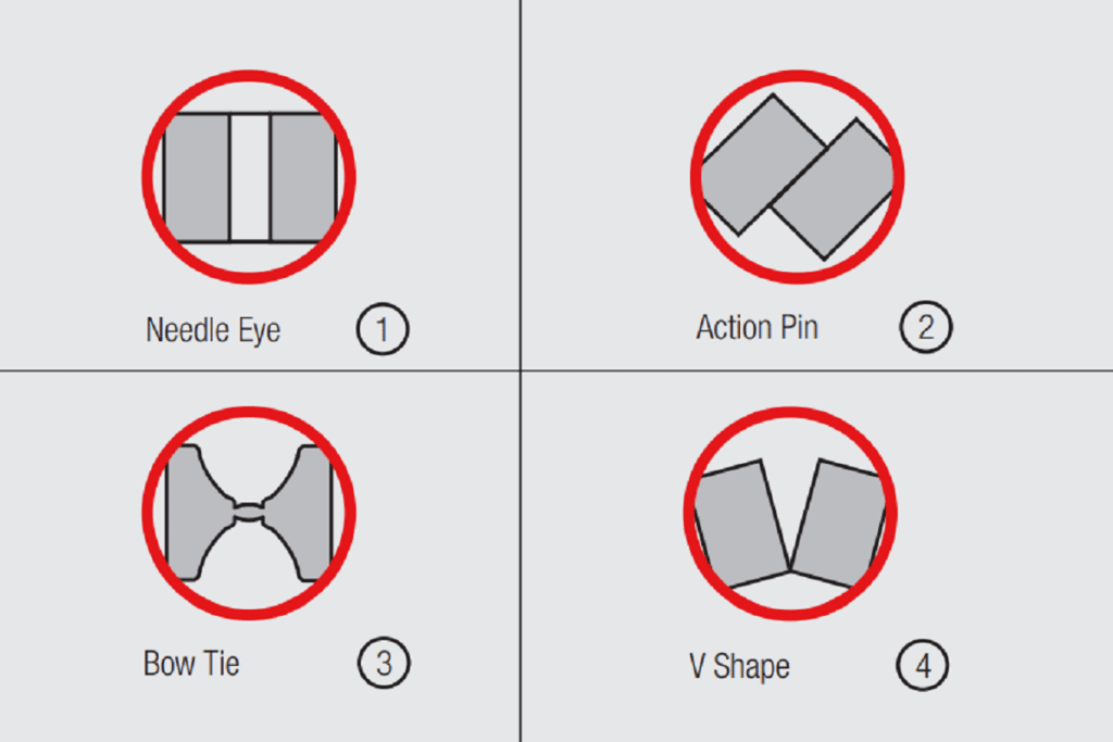
There are many different compliant section designs in use today. The inserted cross sections of four examples are shown in Figure 2.66. “Eye and Needle” Figure 2.66 1, “Action Pin” Figure 2.66 2, “Bow Tie” Figure 2.66 3 and “V Shape” Figure 2.66 4 are the most popular ones. Note that there are several different compliance mechanisms in these designs. The most used is called an “Eye of the Needle” (EN) for reasons apparent in Figure 2.67. The EN compliance is essentially that of a double supported cantilever beam. Figure 2.67a shows the original compliant section and 2.67c the deflected compliant section of an EN compliant pin fully inserted in a PTH. Given the board rigidity, noted above, the deformation on insertion is primarily in the compliant section of the pin. The relationship between the compliant section dimensions, both width and length, and the diameter of the PTH control the amount of deflection and, therefore, the residual force between the compliant section of the pin and the PTH wall.

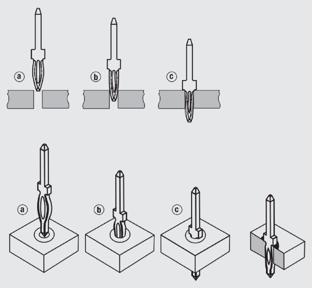
Recall that the objective of a connector is to create and maintain an appropriate magnitude and distribution of metal-to-metal contact areas at all interfaces. Consider the contact areas in a compliant pin connection. Figure 2.67 shows the linear contact areas between the length of the compliant section and the wall of the PTH in a longitudinal cross section. There are at least two longitudinal contact interfaces, one at each beam of the compliant section. The transverse cross sections in Figure 2.66 show contact areas along the width of the compliant section. Again, there will be at least two transverse contact areas. The sum of these areas determine the total contact area between the PTH and the compliant section. The area so generated will be much larger than that of typical separable interfaces and, thus, the resistance of a compliant pin connection will be significantly lower. With this analysis of contact area creation in hand, attention turns to the generation of contact force to maintain the integrity of the contact area.

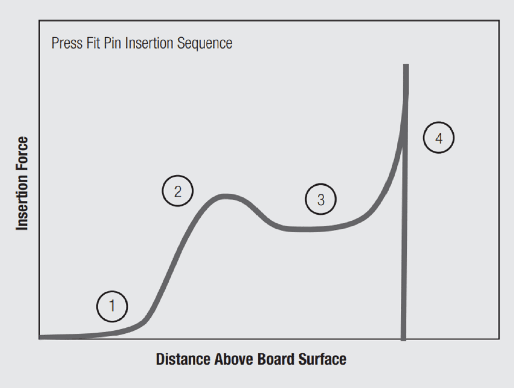
There are similarities between the insertion of a compliant pin into a PTH and the mating of a pin contact into a receptacle socket (discussed in Chapter II/2.2.1 Separable Interface Requirements) but the deflection is in the pin rather than in the beams of the socket contact. The same lead-in frictional issues exist as with pins and sockets. In this case the lead-in geometry of the compliant section of the pin determines the effective entry angle because the geometry of the PTH is constant. Figure 2.68 schematically plots insertion force versus the insertion depth of the compliant section of the pin into the PTH. Note the similarity to the insertion force curve for a separable connector in Figure 2.21.
The initial increase in insertion force comes from the deflection of the compliant section as the lead-in makes contact to the PTH wall, Figure 2.67b. Friction forces change in magnitude and direction as the lead-in entry angle varies until the uniform portion of the compliant section slides against the walls of the PTH when the insertion force plateaus, as it does in the separable connection when the receptacle beams are fully deflected. The final increase in force occurs when the tooling bottoms against the PCB. There is a significant difference, however, in the magnitude of the forces. Compliant pin insertion forces are in the range of several kilograms while separable connection insertion forces are typically a few hundred grams. The residual contact forces that create and maintain the integrity of the metal-to-metal contact interfaces between the compliant pin and the PTH are also of the order of kilograms, compared to the hundred or so grams of a separable connection. So, in addition to a lower resistance because of the larger contact area, the integrity of the contact interface is also superior because of the higher residual contact force.


Consider now the dimensional relationships that determine the deflection mechanics and, therefore, the performance of compliant pin permanent connections. Refer back to Figure 2.67 and note the original width, Wo, of the compliant section as compared to the diameter of the PTH. Clearly the PTH diameter must be less than Wo for the compliant section beams to be deflected on insertion. Figure 2.69 shows a cross section of a PTH. Note that there are several “diameters” in the figure. The basic diameter is that of the drilled hole in the PTH. This is the critical dimension as it defines the deflecting surfaces, the rigid PTH wall that determines the deflection of the compliant section. Despite the importance of the drilled hole diameter, the PTH dimension is usually specified by the finished hole diameter, the diameter after plating, because that is the diameter that is readily measured. All PTH will have a copper plate, with a typical thickness in the range of 25 to 75 µm (1000 to 3000 microinches). The secondary plating for compliant pin applications, if any, is generally tin/tin-lead in the range of 5 to 15 µm (200 to 600 microinches). The tin plating thickness influences the insertion force, due to the higher coefficient of friction of tin as compared to copper, but has little effect on the residual contact force.
As noted previously, the residual forces in compliant pins are significantly higher than those of separable connections. Recall that high normal forces in separable connections affect the wear, the mating durability, of the contact finish. In compliant pins the concern about the effect of high forces is on the magnitude of the pin insertion force and the potential for damage of the plating in the PTH. For reference, the insertion forces for a compliant pin in a nominal 1.0 mm finished hole are in the range of 50 to 250 Newtons per pin. A minimum retention force of 30 Newtons is also specified for this hole size.
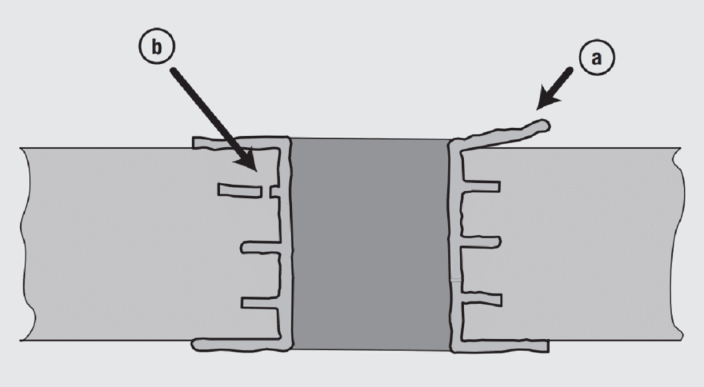
The PTH damage due to such high insertion forces can include lifting of the annular ring around the PTH (Figure 2.70a), radial hole distortion and fracture of the bond between an inner layer trace with the PTH plating (Figure 2.70b). In addition to these force effects, damage to the PTH is dependent on the compliance of the pin and the contour of the edges of the pin that make contact to the PTH plating.

The finished hole diameters for compliant pin applications have decreased dramatically since their introduction in the 70’s. At that time the finished hole diameter was nominally 1.5 mm (0.06 in). In the 80’s and 90’s the finished hole diameters decreased to nominal 1.0 and 0.6 mm (0.04 and 0.024 in) respectively. Recently holes in the range of 0.2 mm (0.05 in) have been introduced. As an example of hole tolerances, for a nominal finished hole of 1.0 mm the tolerances are +0.09 and –0.06 mm. The corresponding drilled hole dimensions are 1.15 mm ±0.025 mm. Naturally, these tolerances vary with hole size. The reduction in PTH dimensions were necessary to open new markets for compliant pins as electronic equipment increased in functionality and decreased in size.