
The majority of connector contacts are manufactured from copper alloys due to the combination of high electrical conductivity and good mechanical strength and formability characteristics. This section will provide an overview of copper alloy metallurgy to explain how those characteristics are obtained and used in the manufacture of connector contacts.
Copper Alloy Metallurgy
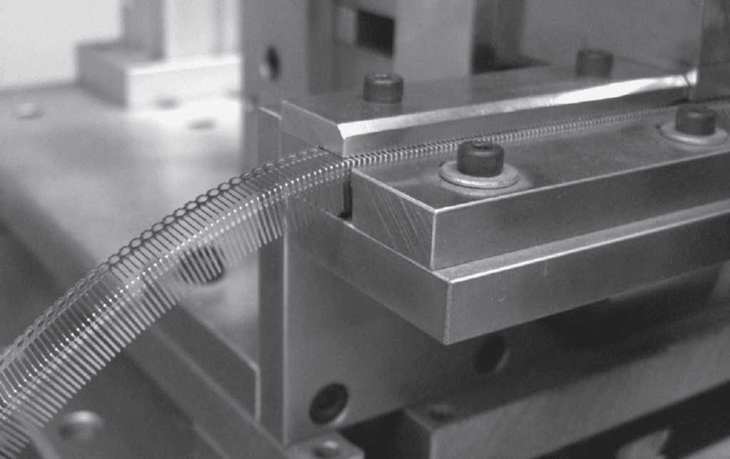
With the exception of silver, copper has the highest electrical conductivity of any metal. Mechanically, copper has moderate strength and good formability. Formability refers to the ability to take a metal and bend or form it into various contours, such as the connector receptacle contacts shown in Figure 1.25, without cracking. By adding other elements into the copper matrix, alloying, the mechanical characteristics of copper can be improved significantly without unacceptable loss in formability. The changes in mechanical performance characteristics depend on the alloying element, e.g. tin, zinc or beryllium, and the amount of the alloying element added to the copper. Most copper alloys used in connectors are lightly alloyed with alloy contents of less than ten percent. Cartridge brass, arguably the most common contact material due to heavy use in white goods and industrial applications, is the major alloy with a higher alloy content, being nominally 70 percent copper and 30 percent zinc.

The improvements in mechanical performance, however, are accompanied by a significant decrease in electrical conductivity. A common benchmark for the electrical conductivity of copper alloys uses the International Annealed Copper Standard, IACS, as a reference. Against this standard, copper has a conductivity of 102 percent IACS while phosphor bronze, copper/5%tin has an IACS conductivity of 20 percent, a significant decrease. Even at these conductivity levels, however, copper alloys are still highly conductive. For comparison the conductivities of aluminum and nickel, in IACS values, are 61% and 16% respectively.
Consider now some of the details of alloying of copper with respect to electrical conductivity and mechanical performance. The discussion begins with electrical conductivity effects.
Alloying and Electrical Conductivity
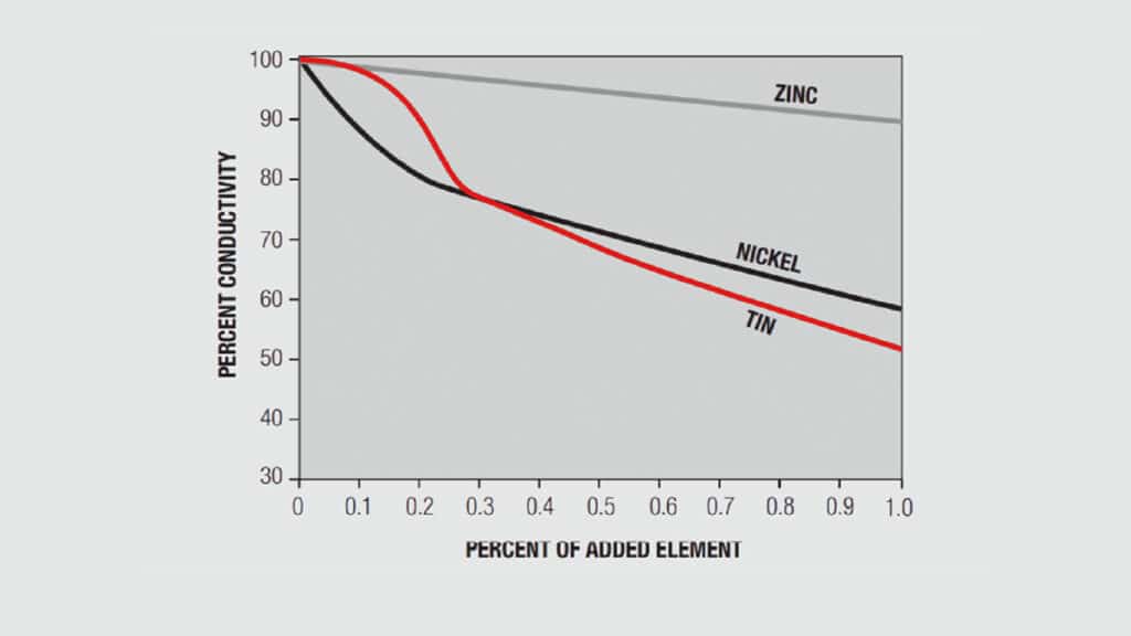
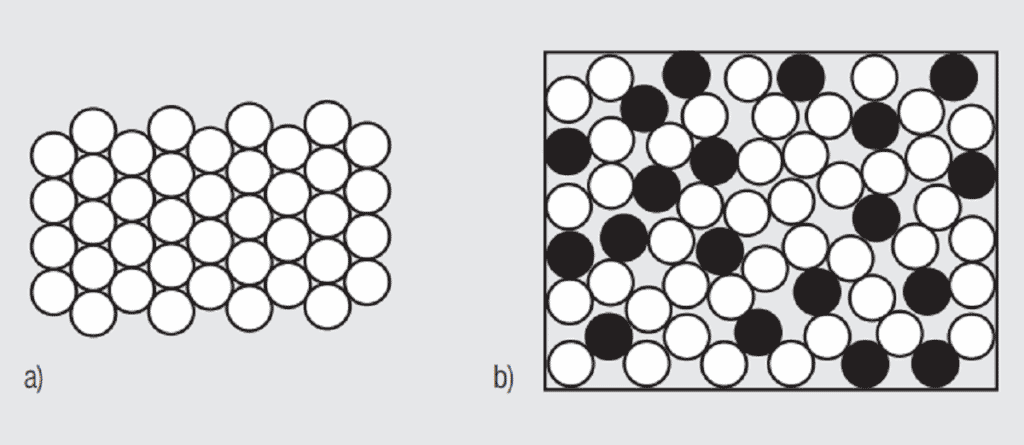
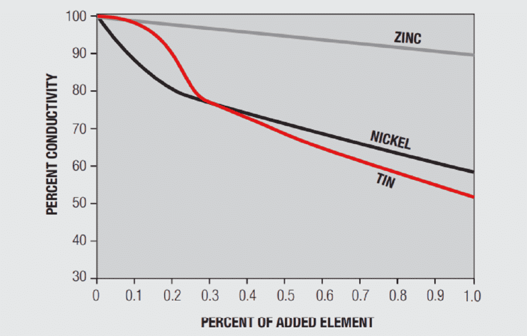
A simplistic, but basically accurate, explanation for the high conductivity of metals is that they contain free electrons, electrons that are not tied up in the inner shells of the atomic structure. When an electric field is applied to a metal, these free electrons are accelerated by the field and result in current flow. While these free electrons are free from individual atoms, they are surrounded by other atom shells which can impede the flow of the free electrons, that is, scatter the free electrons and introduce resistance into the system. In pure copper, all the atoms are on fixed positions in a close packed attice, as schematically illustrated in Figure 1.26a, and this fixed structure introduces a characteristic resistance, the resistance of copper. If other elements are added to the copper they will have different characteristics, size and electronic structure, so they will distort the lattice, as shown in Figure 1.26b, increasing the scattering of the free electrons and, thus, the electrical resistance. The degree of increased scattering depends on the alloying elements and the amount of alloying additions. Figure 1.27 shows the effect of small additions of zinc, tin and nickel to copper.


Alloying and Mechanical Properties
Before discussing the effects of alloying on mechanical properties a discussion of pure metal mechanical properties is in order. Figure 1.28 contains a stress-strain curve for a metal under a tensile, uniaxial, load. The important parameters in the figure are:

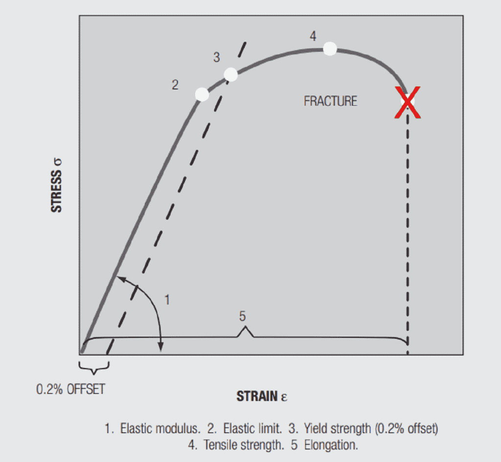
Elastic (Young’s) Modulus, E, is the slope of the stress versus strain curve in the initial stages of loading. Elastic means that if the load is applied and removed the sample will return to its original length. The elastic modulus depends on the material and, in copper alloys, is not significantly affected by alloying. The range in E across the commonly used copper alloys is between 16 to 20.106 psi. In Chapter II/2.2 Contact springs the elastic modulus will be related to the spring rate, the force versus deflection, of a cantilever beam, an important connector design parameter.
Yield strength, is the stress at which a given permanent set, a permanent increase in the length of the sample when the load is removed, is introduced into the sample. For copper alloys the yield strength is generally taken at 0.2 percent offset, that is, the stress at which the length of the sample has increased by 0.2 percent. The value is obtained from the stress-strain curve by drawing a line parallel to the Elastic modulus from the 0.2 percent elongation point on the strain axis. Permanent set is due to plastic, non-reversible, deformation of the sample. Plastic deformation begins when the applied stress is sufficient to cause individual atoms to be displaced from their equilibrium positions in the metal lattice on an atomic scale distorting the local lattice structure. As the distortion increases under increasing stress, groups and planes of atoms, called dislocations, move relative to each other, generally along close packed planes resulting in the macro distortion of permanent set. The introduction of such defects into the lattice makes the lattice more resistant to additional deformation, strengthening the lattice. This strengthening is referred to as “work hardening” because the “work”, the deformation, “hardens”, strengthens, the lattice. All metals, pure and alloys work harden. There is an additional hardening mechanism relevant to both pure metals and alloys, grain size hardening. The copper and copper alloys used in connectors are polycrystalline. A cross-section through a contact would show numerous grains separated by grain boundaries. Figure 1.29 shows two grain size reference photographs. The number with the figure indicates the “average” grain size in the photo. The hardening mechanism of grain size actually comes about due to the grain boundaries. The orientations of the grains on either side of the boundary will be different, so the close packed planes will not be continuous and the dislocation motion will be stopped or inhibited, thus, the material will be strengthened. Clearly the relative amount of grain boundary compared to grain is higher as grain size decreases so the hardening effect is stronger. There are two other hardening mechanisms that come into play due to alloying. These mechanisms will be discussed when the discussion of the stress-strain curve is completed.


The final property of interest in the stress-strain curve is elongation, the increase in the length of the sample under load. The importance of elongation is its relationship to ductility, which, in turn, is a measure of the ability to stamp and form the material without unacceptable damage, i.e. cracking in the bend zones. Yield strength and elongation are inversely related, which is to be expected.
Alloy Hardening Mechanisms
Alloying directly affects yield strength in two ways. First, as noted in the discussion of electrical conductivity, alloying elements distort the lattice structure, creating localized strain fields which strengthen the lattice. This strengthening mechanism is called alloy hardening and depends on the alloying elements. The greater the disparity in atomic size and electron structure between the alloying element and copper, the greater the hardening effect will be. Second, the alloying elements affect the work hardening mechanisms and rates producing a different shape to the curvature of the stress-strain curve in the plastic region which is reflected in the determination of the 0.2 percent offset yield strength. These two mechanisms are active in all alloys. Some alloying elements, however, introduce a new strengthening mechanism, second phase strengthening.
Second phase strengthening depends on the introduction of fine particles, the second phase, into the base metal matrix. There are two second phase strengthening mechanisms, precipitation hardening (PH), and Dispersed Second Phase (DSP). The hardening mechanisms are different in the two cases.
Precipitation hardening produces a distribution of small particles into the copper matrix that are very effective at inhibiting dislocation motion, that is, they strengthen the material. These second phase precipitates form because the solubility of some elements in copper varies with temperature. For example, beryllium has a solubility in excess of 1.4 percent at temperatures above 600 degrees Celsius and the solubility approaches zero at room temperature. If beryllium is taken into solution at high temperature and rapidly cooled, quenched, to room temperature the beryllium remains in metastable solution. Aging at an intermediate temperature causes the beryllium to precipitate out as copper beryllides, an intermetallic compound, CuBe. For this reason, precipitation hardening is often referred to as “age hardening”. Similar precipitation of intermetallic compounds, including some non-copper intermetallics, can be realized. This second phase strengthening mechanism can be both potent, effective at inhibiting dislocation motion, and stable, resistant to thermal degradation. It is the thermal stability of the dispersed intermetallic compounds that allows PH alloys to maintain their strength at elevated temperatures over time. This time – temperature stability, called stress relaxation resistance is an important parameter in high temperature connector performance and will be discussed again in Chapter II/2.2 Contact Springs. In contrast, the residual stresses of work hardening, lattice distortion, that inhibit dislocation motion can be relaxed, diminished, by time at lower temperatures.
In dispersed second phase strengthening the hardening mechanism is an enhancement of the work hardening response of the alloy. The dispersed second phase causes more dislocation generation than would occur at the same deformation without the particles. The effect of the additional dislocations is accentuated as thedislocations interfere with one another, an additional strengthening mechanism. The second phase dispersion is dependent on thermomechanical processing with both temperature and working acting simultaneously to create the dispersion. The dispersed second phase can also result in a finer grain structure, again enhancing the strengthening.