
From its beginnings in the 1940s, crimped connections have been the dominant permanent connection technology for the white goods and industrial markets. This dominance has been realized through the successful field history of crimped connections, A history that is dependent on the consistent use of the crimping system.
The crimping system consists of:
• Wire
• Terminal
• Tooling
The system begins with the selection of an appropriate wire gauge for the application. A typical wire selection criterion is the intended current capacity of the connector in its intended application.
The selected wire gauge then determines the crimp terminals that are suitable for that wire gauge. A crimp terminal may be capable of accepting more than one wire gauge. In this example the terminal, shown in Figure 2.30 can accept AWG 24 up to AWG 18 wires.

Finally, the combination of wire and terminal determines the appropriate crimp tooling and crimping process specifications. A set of tooling may be capable of accepting a range of wire/terminal combinations by varying the crimping process specifications. The tooling, Figure 2.31 used for crimping this wire/terminal, combination can crimp the following wire/terminal: AWG 24 to 18. Details of the crimping process and process specifications will be discussed later in this chapter. A cross-section of a crimp connection using this crimping system is shown in Figure 2.32. This configuration, commonly called a “B” crimp because of its geometry, is the dominant open barrel crimped connection geometry.


There are several important features of interest in the crimp cross-section of Figure 2.32. First note the deformation of the terminal and tooling. All of the conductor strands have been deformed, either against other strands or against the sides of the crimp terminal. The bundle of crimped strands approaches a solid mass of copper conductor. There are multiple contact areas created between individual strands and between strands and terminal wall. These result in a large total contact area and a highly redundant contact area. Note also the deformation of the wings of the crimp barrel as they penetrate the conductor bundle and come together, this wing contact is an important contribution to the performance of crimped connections.

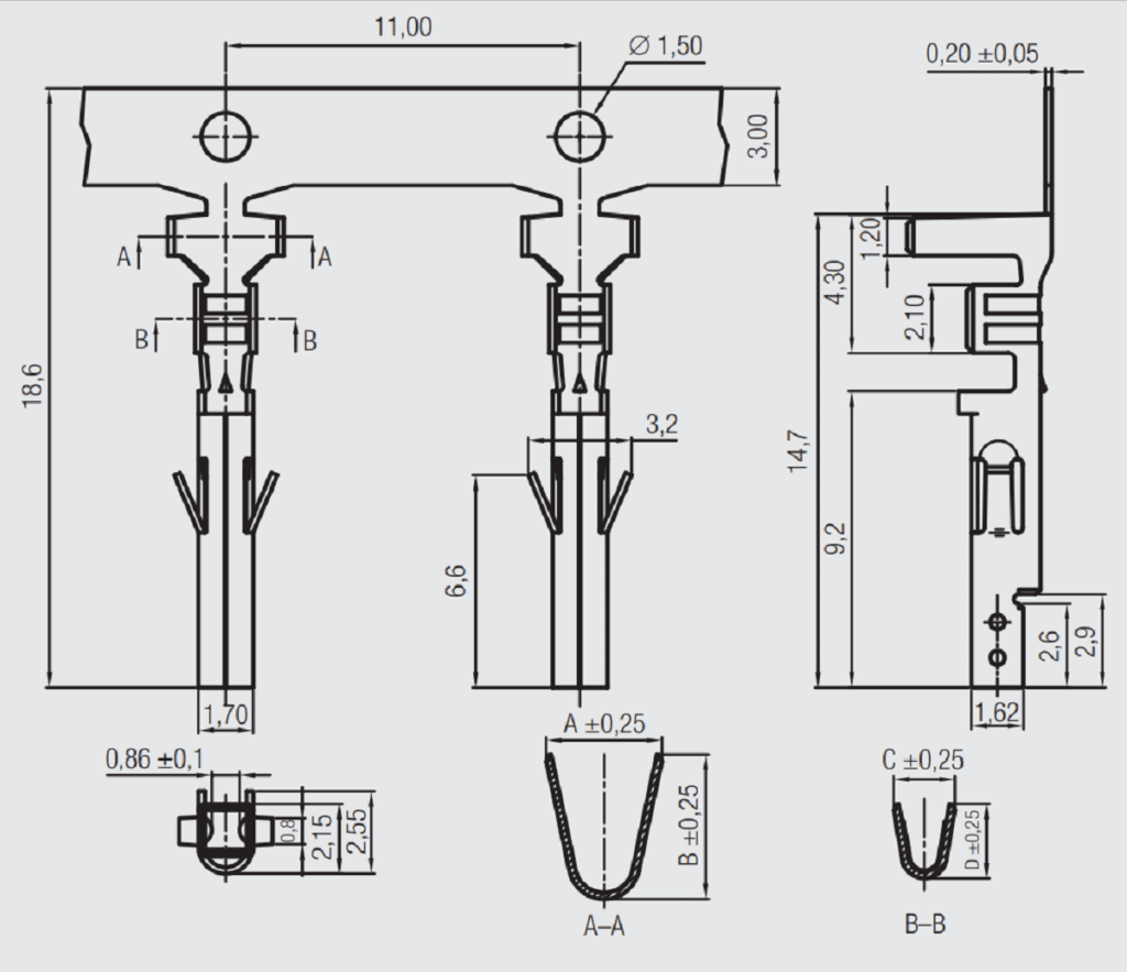
Figure 2.33 shows the original cross section of the crimp barrel. A comparison of the crimped connection cross-section with the original cross-sectional areas of the conductor, the wire gauge, and the cross-sectional area of the terminal in the crimp zone will show that the crimped connection cross-section has a smaller area than the original combined area. This reduction in area indicates that the conductors and crimp barrel have been extruded along the axis of the crimp terminal during crimping. This extrusion creates additional contact area and opportunities for stabilization of the multiple contact areas.
The necessity to control the relative deformation of the conductors and crimp terminal is the reason for the crimping system. Control of the original area, by selection of conductor gauge and crimp terminal, and control of the final crimped cross-section area by the envelope of the crimp tooling as it creates the deformation allows for a consistent and operator independent deformation mechanism. This capability for consistency is the reason for the excellent performance history of crimped connections in the field as noted earlier.
With this overview as a context attention turns to details of the crimping process.
Crimp Terminals
There are two basic types of crimp terminals, closed barrel and open barrel as illustrated in Figure 2.34. The most dramatic difference between the two cases is the presentation of the stripped wire to the terminal. (The strip length of the conductor is an important process control as will be discussed in the discussion of crimped connection inspection.) For closed barrel terminals the conductor must be presented axially, Figure 2.34a. The target area for insertion is the cross-sectional area of the inside of the crimp barrel. In contrast for an open barrel terminal the conductor can be presented from above, Figure 2.34b, and the width of the “U” shape of the crimp barrel rings provides a significantly larger target area. This simple geometric consideration explains why open barrel terminals are used in high volume automatic crimping equipment. Closed barrel terminals are used in semi-automatic equipment, often with hand presentation of the conductor and with hand tooling in lower volume applications

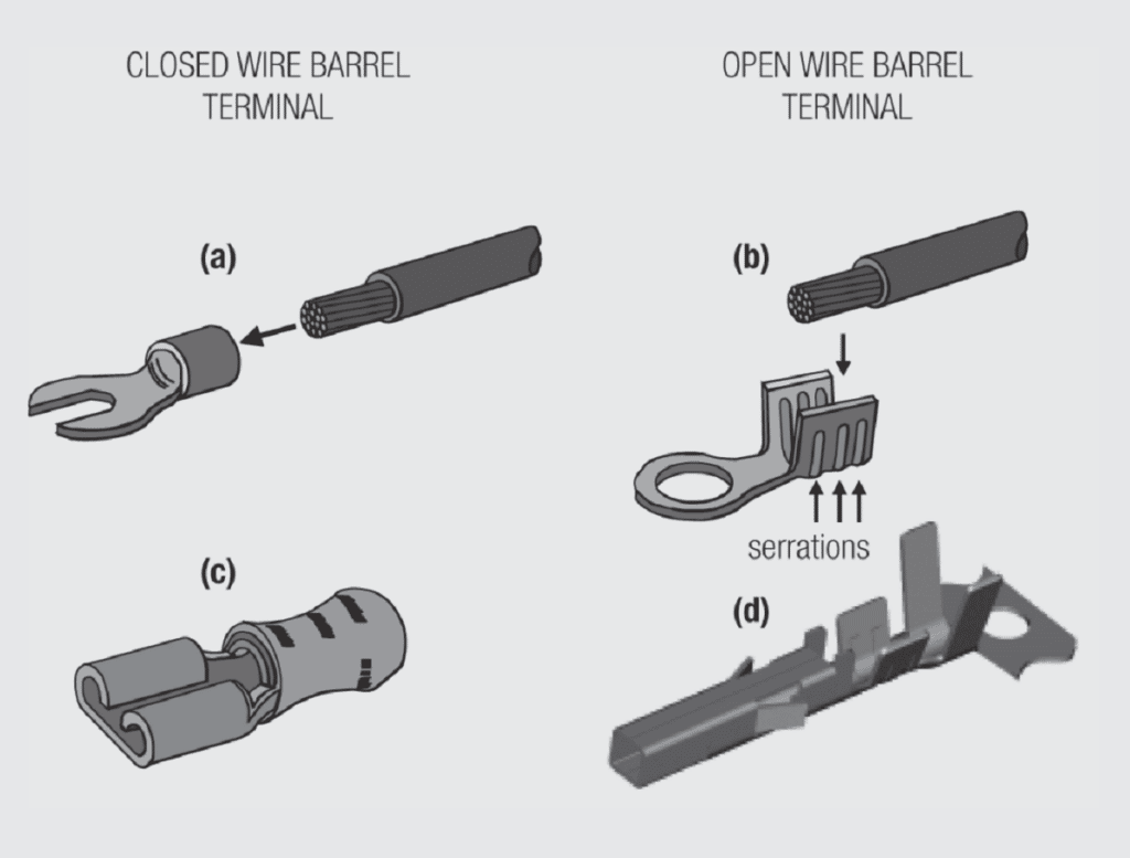
Figure 2.34c illustrates a pre-insulated closed barrel terminal. Pre-insulated terminals provide protection against shorting between contact positions in terminal blocks as used in white goods and industrial applications. The plastic pre-insulating sleeves may be color coded to indicate the wire size. Some pre-insulated terminals include an internal copper sleeve to facilitate insulation support crimping in addition to the insulating plastic sleeve.
Figure 2.34d shows an open barrel crimp terminal that also includes an insulation support barrel. All crimp terminals will have a crimp barrel where the electrical permanent connection is made. The crimp barrel shown also contains serrations, shallow grooves in the crimp barrel. Serrations serve to enhance the integrity of crimped connections as will be discussed later in this chapter. The purpose of the insulation support barrel is to provide a strain relief to reduce the stresses transmitted through the conductors to the crimp barrel during vibration or mechanical disturbances in the field. Insulation support crimps may be either compression, where the insulation is lightly crimped, or overlapping, where the wings of the insulation barrel wrap around the insulation of the wire.
Figure 2.35 shows conductor and insulation crimps and the corresponding cross sections. Note that the insulation crimp merely grips the insulation, in this case through compression. In some cases the insulation barrel is referenced as an insulation grip for this reason.

insulation grip crimp (bottom)
The Crimping Process
As noted, open barrel terminals are generally crimped using high volume automatic crimping equipment while closed barrel terminals are generally crimped using semiautomatic or hand tooling. The kinetics of the crimping process with respect to the deformation of the conductors and crimp barrel, however, are very similar for both terminal styles, and both take advantage of the consistency of the crimping system of wire, terminal and tooling. The following discussion will use open barrel crimping as an example.
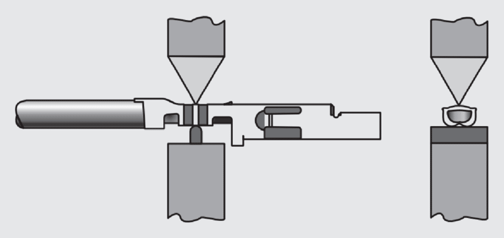
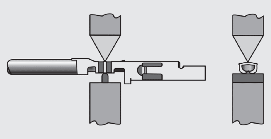
Figure 2.36 shows three steps in the crimping process. The first figure shows the containment of the conductor strands and the engagement of the wings of the crimp barrel with the lead-in section of the crimping tooling as the crimping process begins. In the second figure, compression of the strands begins as the wings fold over in the forming section of the tooling. Forming of the wings around and into the strand bundle is a critical part of the crimping process as will be discussed. The final figure shows the total deformation of the strands and the crimp barrel in the completed crimp. Control of this final stage of the crimping process provides the desired control of the overall crimping deformation and geometry. Control of these parameters is critical to the integrity of the crimped connection as will be explained in the following discussion.

Crimping Deformation and Crimped Connection Performance
As discussed in some detail in Chapter I/1.3.2 The Mechanical Interface: Friction and Wear/Durability, the deformation of two surfaces as they come in contact with each other determines both the electrical and mechanical characteristics of the interface between them. During the crimping deformation multiple interfaces are created as the conductor strands deform against one another and against the walls of the crimp barrel. Consider first how the crimping deformation affects the mechanical strength, the pull strength, of the crimped connection.
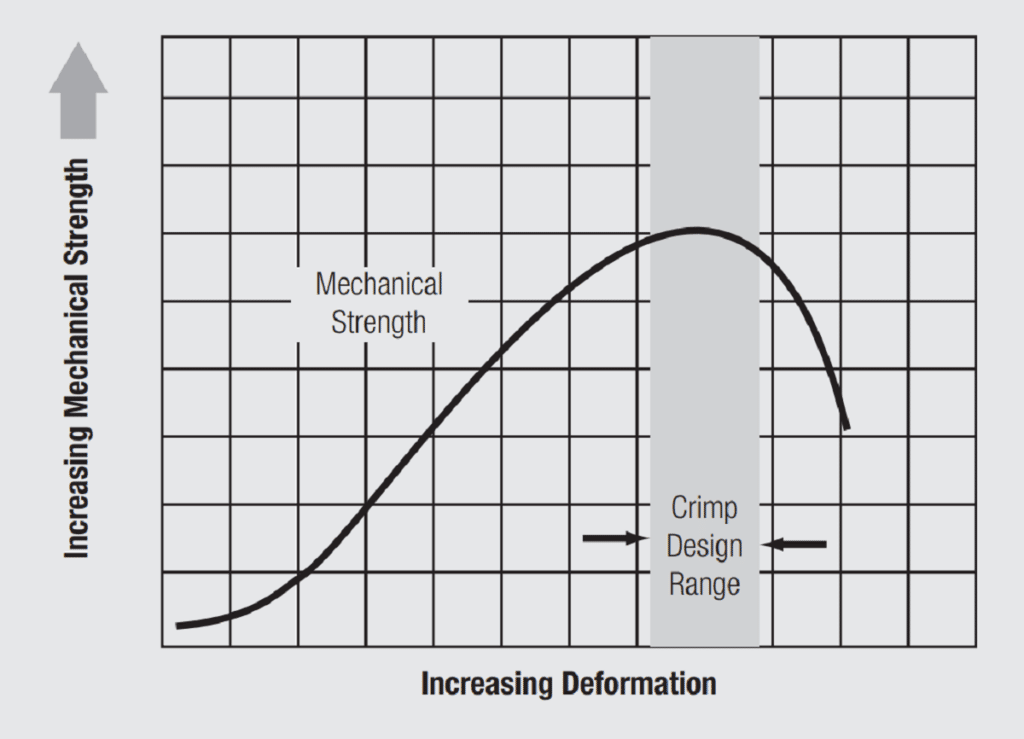
Figure 2.37 schematically illustrates the pull strength as a function of deformation during crimping. The initial pull strength is essentially zero as the conductors are simply sitting in the crimp barrel. As deformation begins friction forces are created between the strands and the strands and the crimp barrel and the pull strength begins to increase. As the conductor strands deform, and as they wipe against the walls of the crimp barrel, surface films and contaminants are displaced and metal-to-metal contact interfaces are generated as previously discussed. As deformation continues the number of interfaces and the average size of the interfaces increases. The friction forces, work hardening and cold welding at the interfaces also increase. Eventually the bonding between the strands and the crimp barrel increases to the point where the strands and crimp barrel approximate a solid mass and the pull strength levels off. The decrease in pull strength occurs when the cross-sectional area of the strands and crimp barrel becomes smaller than the original combined area of conductors and crimp barrel.

Obviously the same description of interface formation applies to the electrical contact interfaces. Figure 2.38 schematically illustrates the change in crimp conductivity with crimping deformation. The increase in conductivity is due to the increasing contact area. Once again, at some point in the deformation the multiple redundant contact interfaces areas reach a cumulative area where these contact areas are essentially equivalent to the full cross sectional area of the crimp barrel and conductor system.
This is analogous to the “full area contact” of a separable contact interface as discussed in Chapter I/1.3.2 The Mechanical Interface: Friction and Wear/Durability. This is the reason for the plateau in the conductivity versus deformation curve. Conductivity increases incrementally beyond this “full area contact” region. The decrease in conductivity comes when the crimped cross sectional area drops below that of the original conductor plus crimp barrel area.

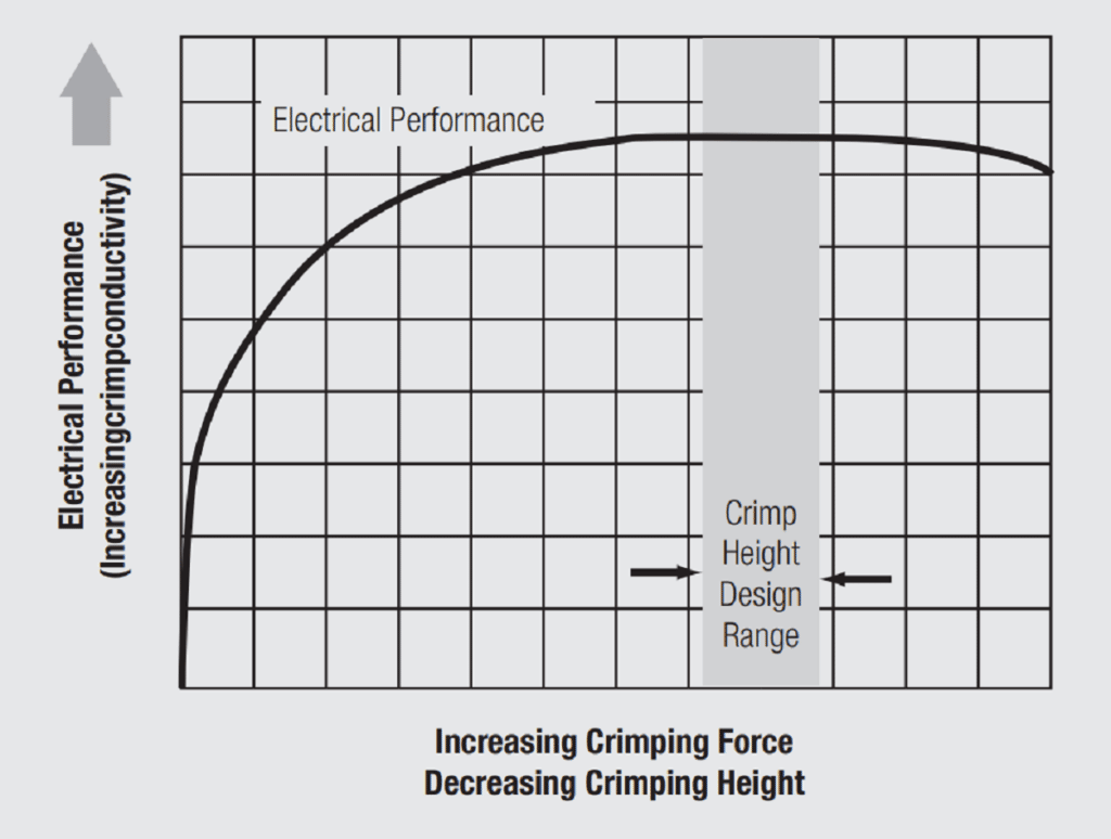
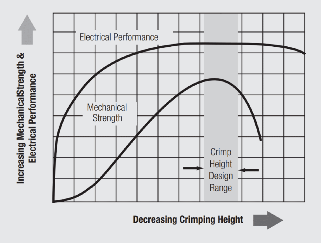
Figure 2.39 plots both pull strength and conductivity as a function of deformation on the same graph. In this figure deformation is characterized by crimp height, basically the parameter that controls the overall deformation during the crimping process. Crimp height will be discussed in detail during the discussion of crimp inspection methodologies. Note that the very broad plateau in conductivity overlaps the much narrow mechanical strength curve. Thus crimp deformation can be controlled to optimize mechanical or electrical performance. In the early days of crimping technology the tendency was to optimize mechanical performance, in particular to ensure that connections were not overcrimped, that is on the falling side of the mechanical strength versus deformation curve. In part this was to allay concerns that the deformation during crimping was not “cutting” the strands. The failure mode for crimped connections on the upside of the curve tends to be by pullout of the strands. On the downside the failure mode is conductor breaks, inside or outside the crimp barrel. Pullout failures clearly indicated that the conductor strands were not being “cut”. As field history of successful crimped connections was accumulated, optimization of electrical performance tended to be emphasized and crimping deformations were increased. A commonly used gauge for deformation is the Area Index, the ratio of the cross-sectional area of the crimped connection to the original cross-sectional area of the conductors and the crimp barrel. Area index recommendations fall in the range of 70 to 85 percent with the lower ranges applying to automated crimping processes and the upper to hand tool applications.

Crimp Integrity
The discussion in the previous section has highlighted how the multiple redundant contact interfaces between conductor strand and between conductor strands and the crimp barrel are created. These interfaces, however, are small and of low mechanical strength individually. To provide consistent field performance these multiple contact areas must be protected so as to function collectively. The excellent field performance history of crimped connections testifies to the fact that this condition has been realized. There are several crimp connection design parameters that provide this protection on a consistent basis. These include residual forces in the crimp barrel, mechanical confinement by the crimp barrel and mechanical confinement/interlocking due to serrations in the crimp barrel. Each will be considered separately.
Residual Forces
It is clear that both the conductor strands and the crimp barrel experience significant plastic deformation during the crimping process. Despite this plastic deformation, there are always residual elastic stresses in the deformed configuration that tend to spring back towards the original pre-deformation configuration of the materials. In the crimping process, this elastic spring back occurs when the crimp tooling is removed. At this point the crimp barrel and the strands tend to return to their original geometries. The crimp barrel will tend to return towards its original open configuration and length and the conductors will tend to return towards their original cross sections and lengths. The relative spring back of the crimp barrel and conductors will depend on material parameters such as Young’s modulus and yield strength and the geometries of the components. The desirable response is that the crimp barrel tends to respond less than the conductor strands, both radially and longitudinally resulting in a radial compressive stress and a tensile longitudinal stress on the strands. This compressive stress would, in turn, provide mechanical stability to the individual contact areas within the crimped connection.
Mechanical Confinement
If the residual force systems described in the previous section are realized, they will provide a confinement mechanism to retain the integrity of the contact interfaces. A second confinement system can also be created. Note in the crimped cross-section of Figure 2.32, that the wings of the crimp barrel come and close against each other to form the crimped connection. This in itself provides a confinement system for the conductor strands. The geometry of the crimp tooling to form the wings into the crimped connection configuration as well as the material and dimensional characteristics of the crimp terminal will determine how successfully this confinement mechanism can be realized in practice.
Serrations
Crimp barrel serrations provide an independent mechanism for mechanical stability of crimp contact areas. Figure 2.40, show four serrations in a crimp barrel terminal. Serrations provide two benefits. First, as the conductor strands deform into the serrations they wipe along the edges of the serrations. This wiping action displaces surface films and enhances contact area formation. Second, the conductors are deformed into and interlocked between the serrations. This interlocking mechanism provides additional mechanical stabilization in the crimped connection to preserve the integrity of the multiple metal-to-metal contact interfaces in the crimped connection.
Second, the conductors are deformed into the serrations, as shown in Figure 2.40b, and, therefore, are interlocked between the serrations.

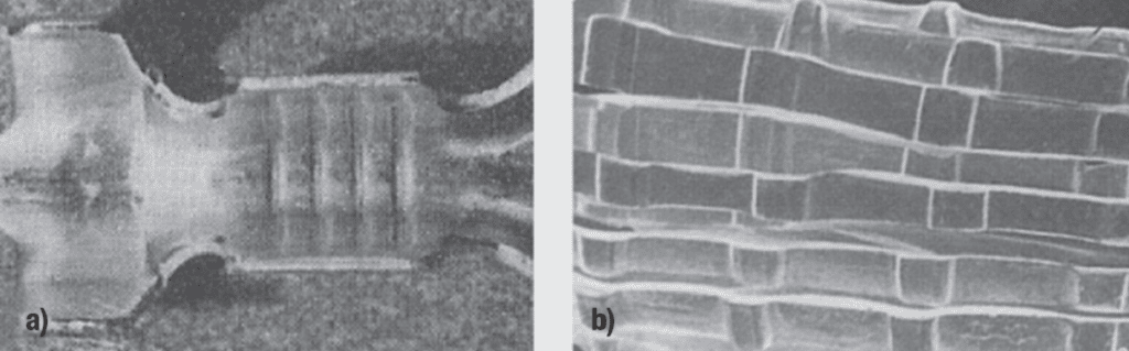
b) Conductor deformation into crimp barrel serrations
To enhance the potential for all of these mechanical stabilization possibilities the crimping process and deformation must be tightly controlled. This is, of course, the intent of the crimping system of wire, terminal and tooling. The wire and terminal combination determines the cross sectional area going into the tooling and the tooling design determines the final cross sectional area of the crimped connection, that is controls the amount and geometry of crimping deformation.
Crimped connection geometries
As would be expected, crimped connection geometries are different for open and closed barrel terminals. Recall that the “B”, Figure 2.32, crimp is the most common geometry for open barrel terminals and dates back to the 1950’s. Figure 2.41 schematically illustrates some common closed barrel crimped connection geometries. The “B”crimp is the most standard in the industrial or consumer applications but the “hexagon” crimp, Figure 2.41b, is commonly used in high current applications, while the “4 indent”, Figure 2.41c, is used in military or aerospace applications.

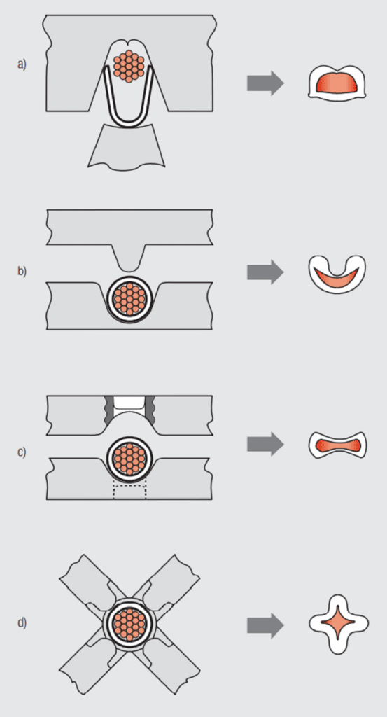
The W crimp dates back to the 1940, and is still commonly used in larger wire sizes and for high current applications. The indent crimp geometries are more recent and are used in military and aerospace applications.
Crimped Connection Inspection Practices
Inspection of crimped connections performs two functions. First, it validates that the crimping process was properly performed. Second, the data may be used to monitor any trends and/or deviations in the crimping process over time. There are three different crimp inspection methodologies, visual, to ensure the process was followed, crimp height, to ensure that the crimping deformation was properly controlled and pull strength, to validate the consistency of mechanical performance.
Consider each separately.
Visual Inspection
Figure 2.42 highlights several visual inspection practices and criteria. The rationale for each practice follows.

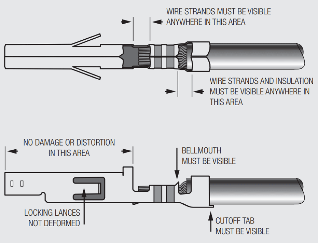
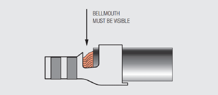
The comments attached to the top drawing in Figure 2.42 relate to the stripping of the insulation from the wire and the placement of the stripped wire into the terminal. The requirement that wire strands and insulation be visible between the insulation barrel and the crimp barrel is to ensure that the insulation has been properly stripped and the wire properly inserted into the barrel. If no wire strands are visible the strip length may have been too short such that insulation may have been included in the wire barrel on insertion. If this is the case, the insulation will be extruded throughout the crimp barrel during crimping and will compromise the mechanical and electrical performance of the crimped connection. If no insulation is visible, the wire strip length may have been too long so that the insulation does not fill the insulation barrel and the bend protection of the insulation crimp is compromised. The requirement that conductor strands be visible between the crimp barrel and the contact section of the terminal has a similar function. If no conductor strands are visible the strip length may have been too short. The conductor strands should also not abut or extend into the contact area which would indicate the strip length was too long. Damage to the insulation and conductors during stripping may also be noticed at this point. Although this evaluation usually takes place independently prior to wire insertion into the terminal.
The comments attached to the lower drawing in Figure 2.42 are intended to ensure that the terminal was not damaged during the crimping process. No damage or distortion of the contact area is allowed because the insertion of the pin contact and, therefore, the contact force may be compromised. Damage to the locking lance may affect the mechanical stability of the socket in the housing and, subsequently, the mechanical stability of the contact interface due to vibration and shock in the application environment. The check for the cut-off tab is to verify that the insulation crimp barrel has not been damaged with potential effects on its strain relief function.
The comment “Bellmouth must be visible” is a check for the presence of an additional means of mechanical stabilization not previously described. The angle of the bellmouth creates a friction force to oppose the retraction of the extruded conductor strands into the crimp barrel when the crimp tooling is removed.
Crimp Height
Crimp height is arguably the most important crimped connection inspection practice. As noted previously control of the crimp deformation is critical to crimped connection performance and crimp height provides a means to both control and monitor that deformation. Figure 2.43 schematically illustrates the methodology of crimp height measurement. The crimp height should be measured at the highest point on the base of the crimp terminal. Crimp height tolerances depend on wire size.

It should be noted that crimp height measurements are made continuously during high volume automatic crimping production. Deviations from crimp height specification cause the machine to shut down. In some equipment crimp force is similarly monitored.
Pull Strength
Pull strength testing may be destructive for quantitative analysis of the pull strength, or go no-go to validate that minimum pull strength has been realized. In either case, care must be taken to ensure that the applied load is uniformly distributed among the conductors. A commonly used practice toward this end is to wrap the wire around a square post prior to applying the load.
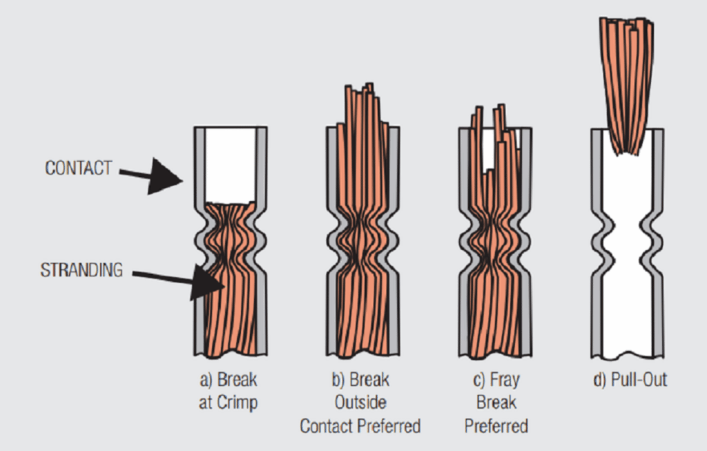
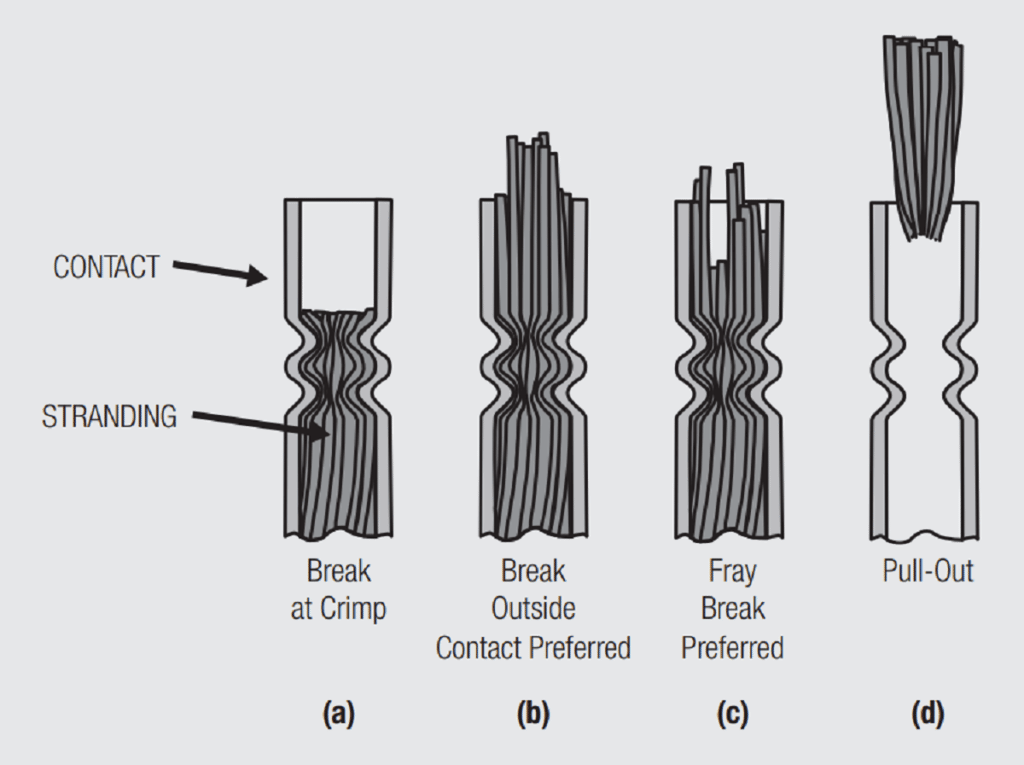
As noted previously, in samples pulled to failure the failure, mechanism depends on the crimp height used for the crimping process and whether the deformation is on the increasing or decreasing side of the pull strength versus deformation curve. In some cases the failure mechanism is the basis for acceptance of the crimping process. Figure 2.44 shows four different failure mechanisms. In 2.44a the conductors break in/at the crimp zone. Such failures may indicate excessive deformation, and work hardening, of the conductors during crimping. In 2.44b and c, the conductors break away from the crimp zone indicating that the break strength of the conductors was realized. In 2.44d, the conductors pull out of the crimp barrel. Such failures indicate that the crimp deformation was on the increasing side of the pull strength versus deformation curve.

In some cases pull strength, either go/no-go, or periodic break strength/mode are used to qualify a crimping process. It is more common, however, to use monitoring and control of crimp height as process control and qualification parameter.
Summary
The key point of this discussion of crimped connection technology is to highlight the importance of the crimping system of wire/terminal/ tooling as a means to ensure consistent control of the deformation during the crimping process. Controlled deformation, in turn, ensures the creation and integrity of the multiple metal-to-metal contact areas created between the conductor strands and between the strands and the crimp barrel during crimping.
Crimped Connection
The consistent field history of crimped connections is a result of the proper application of the crimping system of wire, terminal and tooling. The system begins with the selection of an appropriate wire gauge, generally based on the current capacity requirement of the application. Once the wire is selected the next choice is the crimp terminal. There are different styles of crimp terminals intended for use in a variety of applications as will be discussed. A crimp terminal will generally be suitable for a range of wire gauges. After choosing the wire and terminal, the final decision is selection of the appropriate tooling to make the crimped connection. Tooling selection is also application dependent in the sense that various levels of tooling automation, from hand crimping tools and semi-automatic presses to fully automated high capacity crimping systems, are available.
The reason that the crimping system is so important is that the performance of crimped connections is dependent on the controlled deformation of the wire conductors in the crimp barrel, as discussed in Section 2.2.2.2 Crimped Connections in the text. The wire gauge and the crimp barrel dimensions determine the original amount of conductor material in the crimp and the tooling determines the amount of deformation of that material and the geometry of the final crimped connection. Control of the deformation during crimping determines both the electrical and mechanical characteristics of the crimped connection.
Component Selection
Wire
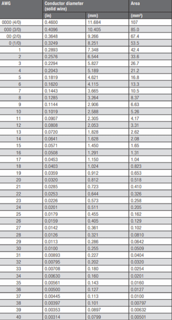
The majority of crimped connection applications use stranded annealed copper conductors. Within a given wire gauge the number and diameter of the individual strands can vary. For example a solid 16AWG conductor has a cross-sectional area of 2.03E–3 in2 while the range of cross-sectional areas for stranded 16AWG conductors is (1.91–2.22)E–3 in2 . As mentioned earlier, wire gauge selection is primarily based on the current capacity for the series of wire gauges.

Conductors may be bare (unplated) or plated, generally with tin, depending on the application. The performance of bare and tin plated conductors is comparable with respect to crimping. For completeness it should be noted that the insulation type and thickness is also variable across a given AWG. The insulation does not affect the crimping system because it is stripped prior to crimping, but it can influence the design of crimp terminal strain relief features. Insulation stripping practice varies from hand stripping of individual wires to semi-automatic stripping to high volume automatic stripping within an overall crimping system. While wire stripping is simple in principle, care must be exercised to ensure that the insulation is cleanly cut to the appropriate strip and that the individual conductors are not damaged during insulation stripping. The two most important examples of conductor damage are cutting of individual strands and displacement of individual strands from the conductor bundle as will be discussed later. The effect of cut or displaced strands is to reduce the amount of conductor area that is inserted into the crimp barrel which, in turn, will change the deformation of the conductor/crimp barrel during the crimping process. The stripping length has to respect the specifications given for each individual terminal.
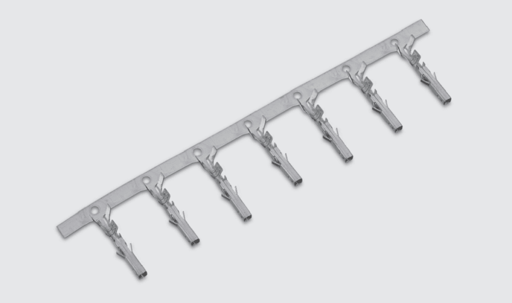
Terminal
A WR-WTB plug crimp terminal is shown in Figure 2.45.

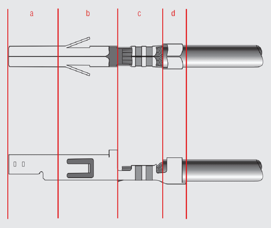
This terminal has a separable interface beam (a), a transition zone (b), a crimp barrel (c) and an insulation grip (d). The separable interface contact design, (a), is application dependent and must not be compromised during the crimping process. The function of the transition zone, (b), is to ensure this independence and, in some designs, to provide latching features to secure the terminal in the housing. The terminal shown in Figure 2.45 has an open crimp barrel, (c), so that the conductors can be placed in the crimp barrel from above. This mode of entry facilitates mechanization of the conductor insertion process and allows for higher crimping rates. There are several designs of insulation grips, (d), including a crimp and a variety of wrap around grips. Insulation grip designs are common to many terminals and are independent of the design of the crimp barrels and separable contact beams.
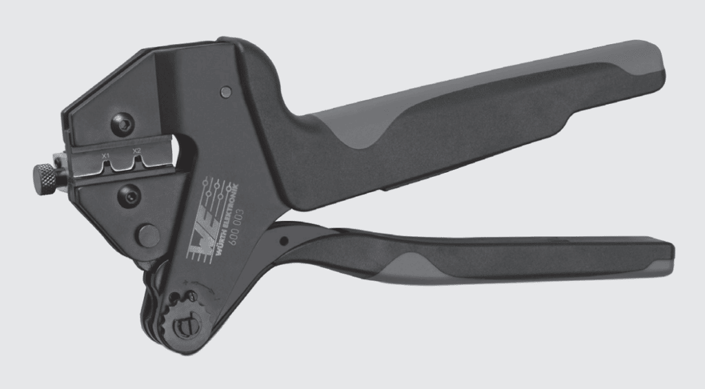
Tooling
As noted previously, tooling varies from hand tools to fully automatic high speed presses for high volume applications. A variety of Würth Elektronik hand tools is shown in Figure 2.46.

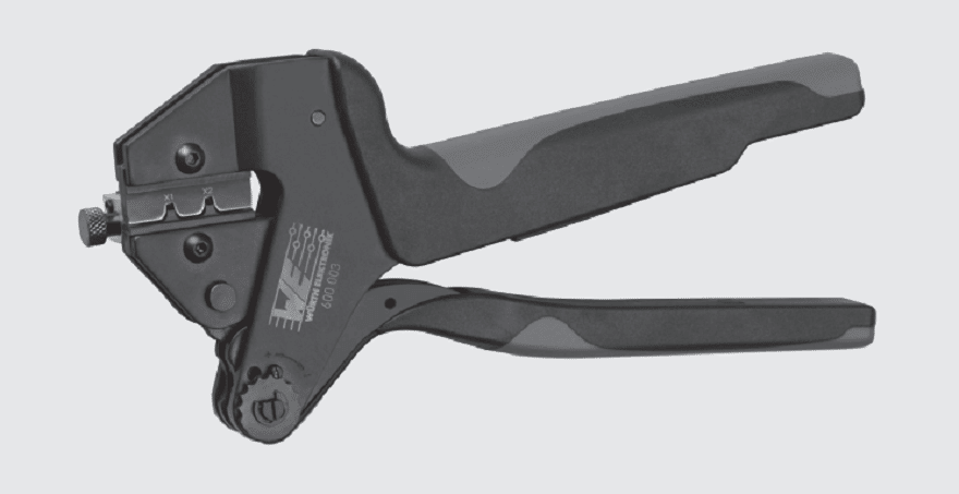
Hand tools are tailored to a crimping system by exchanging the crimping dies in the hand tool body. Some hand crimping tools offer adjustable crimping force and include a stepped ratchet system that ensures that the crimping process is carried to completion. If it is not completed, the tool will not open.
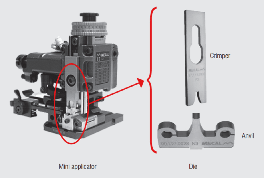
For higher volume applications a semi-automatic or automatic crimping machine with interchangeable dies may be used.
As per the Figure 2.47, an automatic crimping machine needs to have a mini applicator that is made up of a base tool (generally common to all machines) and a die set(dedicated to a terminal).

The Crimping Process
The Crimped Connection
Consider now the crimping system as a whole. Recall that the fundamental purpose of the crimping system is to control the overall deformation of the conductors and the crimp barrel (see Chapter II/2.2.2.2 Crimped Connections, page 111). The following discussion covers the approach to determining an appropriate crimp height, the critical process control parameter for crimping.
Figure 2.48 illustrates the basic factors in the control of deformation during crimping.

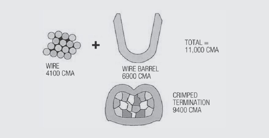
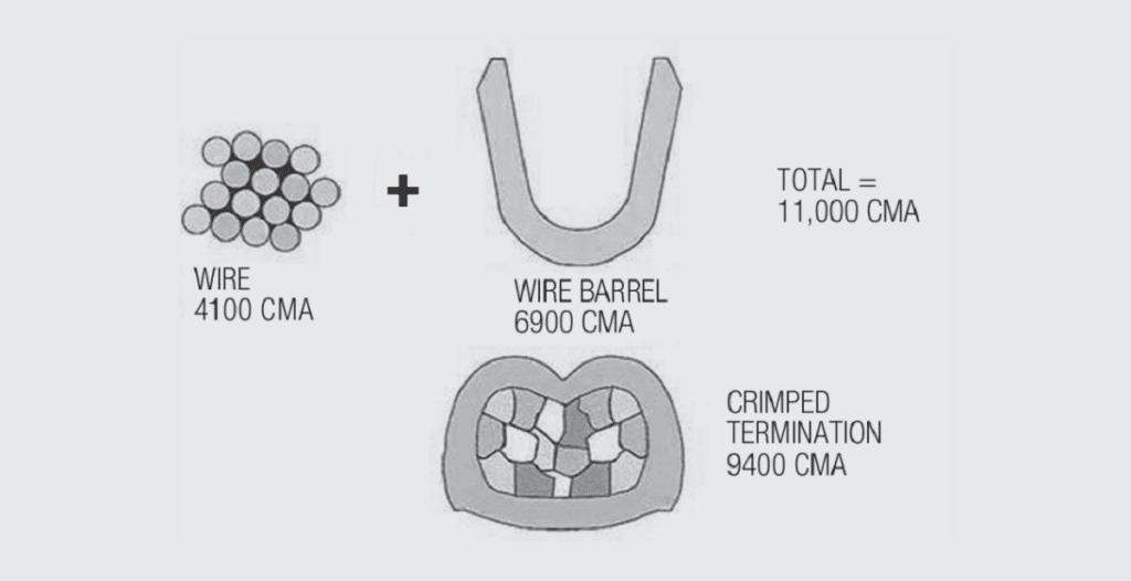
In the early days of crimp technology the cross sectional areas of a crimped connection were calculated in terms of Circular Mil Area (CMA) which is calculated by squaring the diameter of the conductor. For example the CMA (1 CMA, Circular Mil Area is a unit of area equal to that a circle whose diameter is one Mil) of the 16 strand wire shown in Figure 2.48 is given as 4100 CMA, so the CMA of an individual strand is 256 CM yielding a strand diameter of 16 mils (26AWG strands/22AWG wire). The CMA of the cross-section of the crimp barrel, given as 6900 CMA must be calculated from the dimensions of the strip stock and the crimp barrel cross section. This calculation is generally accomplished by using the crimp barrel dimensions noted and the conversion factors:
1 Circular mil = 0.7854 x 10⁻⁶ Square Inch = 5.066 x 10⁻¹⁰ m2 = 5.066 x 10⁻⁶ cm2
In Figure 2.48, the total CMA of conductor and crimp barrel is 11000 CMA. The final crimped cross-section area is given as 9400 CMA, yielding an Area Index (CMAwire-terminal/CMAcrimped connection) of 85% for this example. Recall from the main text that an 85% area index is at the high end of the design zone.
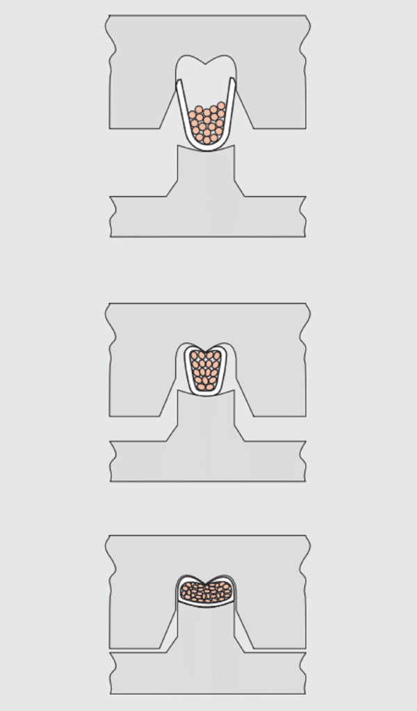
The Crimping Process

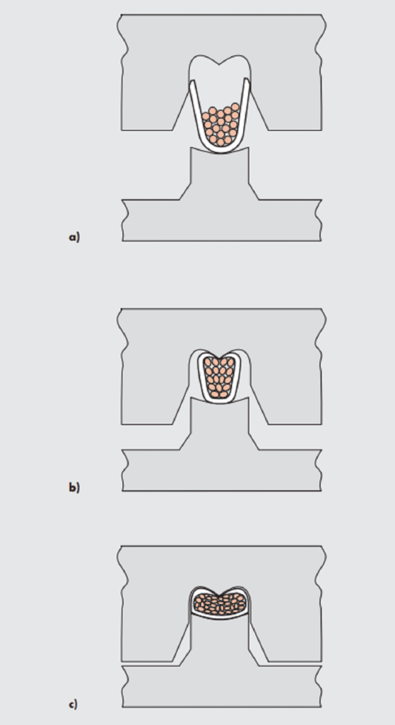
Figure 2.49 shows three steps in the crimping process. Figure 2.49a) shows the placement of the conductor strands in the crimp barrel and the engagement of the wings of the crimp barrel with the lead-in section of the crimping tooling as the crimping process begins. The benefits of the open crimp barrel with respects to conductor insertion are evident. In Figure 2.49b), compression of the strands begins as the wings fold over in the upper forming section of the tooling. Forming of the wings around and into the conductor strand bundle is a critical part of the crimping process to provide the desired control of the crimping deformation. Figure 2.49c) shows the final deformation of the strands and the crimp barrel in the completed crimp. Control of this final stage of the crimping process provides the desired control of the overall crimping deformation and geometry. The shut height of the press at this stage is the means for establishing the crimp height, arguably the most important parameter in controlling the deformation during the crimping process. Control of the shut height is the means for enabling the terminal to accept a range of conductor sizes. Control of these factors, the crimping system, is critical to the performance and integrity of crimped connections.
Crimped Connection Inspection Practices
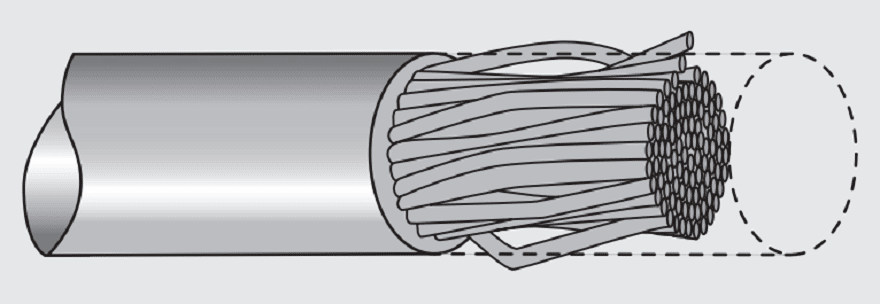
Before beginning the discussion of crimp inspection practices a discussion of wire stripping practices is necessary. There are three commonly used methods for wire stripping, mechanical, thermal and chemical. While the practice of each of these methods is significantly different, the criteria with respect to the resulting stripped conductors are common. As noted earlier, two of the most important aspects of wire stripping practice are control of the insulation stripping and strip length and avoidance of conductor damage or displacement from the conductor bundle. The insulation strip length is specified for reasons to be discussed. Limits on conductor damage or displacement are also specified. Conductor damage includes nicking or cutting of individual strands as shown in Figure 2.50.

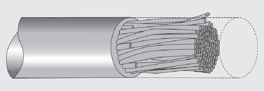
Nicking of strands makes the conductor more susceptible to failure due to mechanical stresses applied to the crimped connection during its application lifetime, in particular, vibration related stresses. Cutting of strands reduces the amount of conductor material inserted into the crimp barrel and, therefore, the amount of deformation produced during crimping which, in turn, can compromise the crimped connection performance in the field. Displacement of conductor strands from the conductor bundle, as shown in Figure 2.51, has a similar effect in reducing the amount of conductor material inserted into the crimp barrel.

Inspection of crimped connections performs two functions. First, it validates that the crimping process was properly performed. Second, the data obtained may be used to monitor any trends and/or deviations in the crimping process over time. There are three different crimp inspection methodologies, visual, to ensure the crimping process was followed, crimp height, to ensure that the crimping deformation was properly controlled and pull strength, to validate the consistency of mechanical performance.
Consider each separately.
Visual Inspection
Figure 2.52 highlights several visual inspection practices and criteria. The rationale for each practice follows.

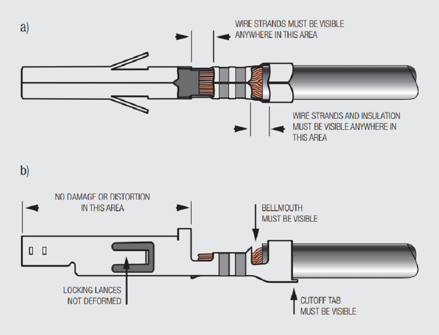
The comments in Figure 2.52a) evaluate the stripping of the insulation from the wire and the placement of the stripped wire into the crimp barrel. The requirement that wire strands and insulation be visible between the insulation barrel and the crimp barrel is to ensure that the insulation has been properly stripped and the wire properly inserted into the barrel. If no wire strands are visible the strip length may have been too short and insulation may have been included in the wire barrel on insertion. If this is the case, the insulation will be extruded throughout the crimp barrel during crimping and will compromise the mechanical and electrical performance of the crimped connection. If no insulation is visible, the wire strip length may have been too long so that the insulation does not fill the insulation crimp barrel and the strain relief function of the insulation crimp is compromised.
In addition to these comments, there should be no visible cut or nicked strands and no individual strands visible outside the crimp barrel. Defects of this type should have been identified earlier in the process after wire stripping.
The requirement that conductor strands be visible between the crimp barrel and the contact section of the terminal has a similar function. If no conductor strands are visible the strip length may have been too short. The conductor strands should also not extend across the transition zone into the contact area which would indicate the strip length was too long.
The comments in Figure 2.52b) are intended to ensure that the terminal was not damaged during the crimping process. No damage or distortion of the contact area is allowed because the insertion of the pin contact and, therefore, the contact force may be compromised. Damage to the locking lance, if any, may affect the mechanical stability of the contact in the housing and, subsequently, the mechanical stability of the contact interface due to vibration and shock in the application environment. The check for the cut-off tab is to verify that the insulation crimp barrel has not been damaged with potential effects on its strain relief function.
The comment “bellmouth must be visible” is a check to ensure the proper location of the crimp zone in the crimp barrel as shown on Figure 2.53.

The bellmouth also has a functional role in that it reduces the potential for the crimp tooling to cause nicking or cutting of strands during the crimping process. A bellmouth is generally required at the conductor end of the crimp barrel with a bellmouth width of the order of one or two times the metal thickness used in the crimped barrel.
A final visual inspection criterion is that the crimped connection does not have a “banana” shape. Excessive longitudinal extrusion of the crimp barrel during crimping, resulting in the “banana”, could compromise the mechanical properties of the crimp in addition to making insertion of the contacts into the housing problematic. An additional extrusion effect is “flash” at the base of the crimp barrel due to extrusion of the crimp barrel material between the walls of the crimping die and the anvil. Excessive flash is an indication of worn tooling.
Crimp Height
As noted previously, crimp height is the most important process control monitor of the crimping process, therefore consistent crimp height measurement practice is also critical.
From Figure 2.54 it can be seen that the two key measurement requirements are the alignment of the crimp barrel wings against the micrometer flat and the positioning of the micrometer tip at the high point on the base of the crimp barrel. Because crimp height tolerances can be as tight as one or two mils, precise measurements are required.
Crimp height has been emphasized because it is an important process control parameter. Crimp width, the distance across the base of the crimp barrel, is also important in determining the crimped connection cross section and, therefore, amount of deformation that occurs during crimping. Crimp width, however, is not a variable in the sense that it is controlled by the design of the crimp tooling and the crimp height.
Pull Force Testing
There are two approaches to pull force testing of crimped connections, pull to failure and pull to specified force value. Pull to failure testing is obviously destructive and may be done periodically to confirm conformance to pull test requirements. Pull force criteria are wire size and application dependent. In either case, care must be taken to ensure that the applied load is uniformly distributed among the conductors in the crimped connection. A commonly used practice to achieve this distribution is to wrap the wire around a mandrel prior to applying the load. Specialized gripping means have also been developed for this purpose.
If the pull force testing is done to failure, the failure criteria will be dependent on the wire gauge. A crimped connection failure typically approaches the wire breaking strength. As noted in the text, in samples pulled to failure the failure mechanism depends on the crimp height used for the crimping process and whether the deformation is on the increasing or decreasing side of the pull strength versus deformation curve. In some cases the failure mechanism is the basis for acceptance of the crimping process.


Figure 2.55 shows four different failure mechanisms. In a) the conductors break in/at the crimp zone. Such failures may indicate excessive deformation, and work hardening, of the conductors during crimping. In b) and c), the conductors break away from the crimp zone indicating that the breaking strength of the conductors was realized. In d), the conductors pull out of the crimp barrel indicating insufficient deformation during crimping. Pull testing values may also be indicative of cut or nicked strands during insulation stripping. Table 2.3 shows the tensile strength.


Conclusion
Crimped connections remain a consistent and cost effective approach to terminating wire and cable when the crimping system of:
Wire: selected primarily for current carrying capacity
Terminal: appropriate to selected wire gauge and
Tooling: selected for the wire/terminal combination is followed.
Once the crimping system is in place the primary process control parameter is the crimp height which ensures the proper amount of deformation of the system to establish and maintain the intended electrical and mechanical performance.