A basic connector product specification, for example, will call out a number of testgroups to assess connector performance with respect to important degradation mechanisms and identify appropriate measurement, conditioning, and exposure sequences. A generic testing program is illustrated below in Figure 2.110.

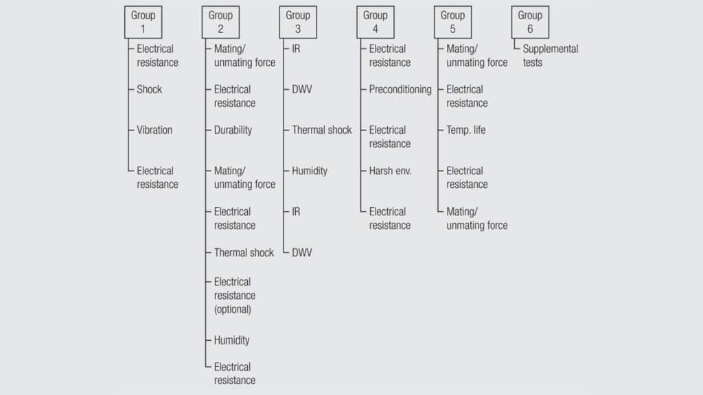
In this test program, Group 1 is a mechanical group consisting of shock and vibration exposures. The shock exposure could be either mechanical or thermal and the vibration exposure could use a variety of test procedures, sine or random vibration applied to one or more product orientations. The measurement called out is electrical resistance which could also be of two types, Low Level Contact Resistance (LLCR) and Contact Resistance at Rated Current (CRRC). Details on these and other conditioning/exposures and measurements will be provided later.
The Group 2 test sequence includes mechanical (durability) and corrosion (humidity) exposures and mechanical (mating/unmating force) and electrical (contact resistance) measurements. This sequence will be discussed in some detail because it is simple in principle, but illustrates some more sophisticated interactions. The first mating/unmating force is a baseline measurement as is the first electrical resistance measurement. Durability cycling is an exposure because it is immediately followed by mating/unmating force and electrical resistance measurements. These measurements will indicate whether the selected number of mating/unmating cycles has affected contact spring mechanical performance. In this case, durability cycling is also a conditioning step in the sense that the second electrical resistance measurement provides the baseline for the next conditioning/exposure sequences. Thermal shock is actually a mechanical conditioning/exposure because rapid differential thermal expansion changes can result in mechanical disturbances of the contact interface. Note the third electrical measurement is optional. If it is made, the thermal shock can be considered an exposure; if it is not the thermal shock is a conditioning step. The samples are then subjected to a humidity (corrosion) exposure and the sequence ends with a resistance measurement. The difference between the second (or third) electrical resistance measurements and the final measurement provides the data for performance evaluation.
It is important to note at this point that test sequences identify appropriate measurements, but generally do not include requirements for evaluation of performance.
Group 3 testing is directed towards evaluation of the housing to validate that the molding processes used have not degraded the polymer electrical performance to an unacceptable level. It includes two measurements, Insulation Resistance (IR) and Dielectric Withstanding Voltage (DWV). The order of these measurements is important because the test voltage for DWV may degrade the polymer over and above any molding degradation and invalidate the original IR measurement causing “good” product to be rejected prior to testing. Thermal shock (mechanical) and humidity (corrosion) are both exposures because mechanical damage to, and chemical degradation of, the polymer can degrade both IR and DWV.
Group 4 addresses environmental degradation and includes electrical resistance measurements, preconditioning step(s) and harsh environment (corrosion). Preconditioning steps for corrosion exposures include durability cycling, to validate contact finish performance, and heat aging, to validate the stress relaxation resistance of the contact spring system. The harsh environment is selected to suit the intended applications of the connector system. For noble metal contact systems MFG exposures are appropriate while tin contact finishes are generally tested using humidity or temperature/humidity exposures. The second electrical resistance is both a screen and a baseline measurement. If the samples show excessive ΔR at this point the test may be terminated, if not the measurements provides the baseline for the corrosion exposure.
Group 5 addresses thermal stability. It includes two measurements, mating/unmating force and electrical resistance. Again, the order is important because mating/unmating can degrade the connector performance so the electrical resistance measurement is a screen and the baseline for performance evaluation. The exposure is temperature life, or heat aging, with the temperature and test exposure times selected on the basis of the product design and application lifetime. Details concerning Temperature/time parameter selection will be discussed later. The final electrical resistance measurement data assesses the connector performance during the test.
Test Group 6 provides an opportunity to specify additional testing or more severe testing of product for specific applications. For example, automotive under-hood applications may require more demanding shock/vibration and temperature life exposures. Marine applications may require additional exposures, for underwater applications or seawater corrosion mechanisms typically not tested for conventional connectors. Traditionally product specifications use parallel test groups in which a set of samples is subjected to a single series of measurement, conditioning, exposure and measurement sequences as discussed. This, of course, does not simulate field conditions where several degradation mechanisms are active, or potentially active, over the application lifetime of the connector. For example, on/off (temperature) cycles are distributed over the product lifetime, unmating/mating (durability) cycles may occur periodically, temperature and corrosion processes may be continuous with variations in severity depending on environmental conditions. For these conditions the appropriate test sequence would be to subject a single set of samples to all the appropriate degradation mechanisms, a parallel test sequence. The complexity of product application lifecycle conditions precludes the definition of a “standard” parallel test sequence, which is one argument for the serial approach which is well defined and allows, at least, a comparative evaluation of connector performance. Parallel testing programs, however, are under consideration.