
This technical blog article written by Alex Guan, KYOCERA-AVX Components Corporation, explains benefits of IDC RF shark fin connectors for antennas vehicle systems.
Abstract
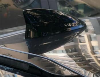
Shark fin antenna units offer an attractive, aerodynamic, and functional way to provide the necessary antennas to the vehicle systems. RF antenna systems use coaxial cables, and the
most common method to connect those cables to the printed circuit board assembly in the shark fin antenna is manual soldering.
Introduction
Modern cars, trucks, and other vehicles have communication and navigation equipment built into them, and all of that equipment requires RF antennas to enhance the signals.
Shark fin antenna units offer an attractive, aerodynamic, and functional way to provide the necessary antennas to the vehicle systems. RF antenna systems use coaxial cables, and the most common method to connect those cables to the printed circuit board assembly in the shark fin antenna is manual soldering.

Because there are generally three or four coaxial cables in a shark fin antenna (AM radio, FM radio, GPS, cellular, etc.), significant labor is required to hand weld each cable conductor to the PCB and each cable braid to GND.
This hand soldering creates a bulk tin dot that is a waste of material and affects the RF performance of the system. It is also difficult to guarantee the quality and reliability of every hand-soldered connection, especially when these connections are subject to the notoriously harsh environments of vehicular transportation like shock, vibration, and high humidity.


IDC, or insulation displacement connector, technology provides a solution to common hand soldering problems. This technology can be applied to RF coaxial cables, promising the best design for long-term reliability across various environments and an excellent solution to replace hand soldering in the shark fin antenna unit. Utilizing IDC technology, KYOCERA AVX has developed a new RF connector for coaxial cables that address these problems — the 6791 series.
IDC Connectors in Shark Fin Antennas

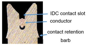
IDC cable connection technology has been applied for more than 40 years. It has been proven reliable for true “gas-tight” termination, suitable for solid or stranded wire, and capable of withstanding automotive temperatures, shock, and vibration. This technology can also be over-molded or potted to make it waterproof and even more reliable. IDC connections work by displacing the insulator on a cable and connecting to the conductors and shield with a simple press.
When a wire termination is made, the wire is pushed down into the IDC contact slot, creating a fresh metal to-metal contact joint gas-tight and preventing gasses or moisture from entering the joint. This connection is then highly reliable and has low resistance. Over-molding or potting can then be done to waterproof the connection for even more reliability. Figure 3 shows a cross-section of this connection.
How to Use 6791 IDC Connectors
The 6791 series of IDC connectors for RF designs offers several advantages. They are low-profile connectors suitable for space-constrained designs. When used correctly, their performance is superior to traditional hand welding assembly.
Specifying and Preparing the Cable
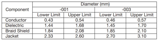
The cable spec is required to properly select the correct connector part number. The proper IDC connector can be chosen using the jacket and conductor dimensions. Example 6791 series
connector compatible cable dimensions are shown in the following table.
As shown in Table 1, KYOCERA AVX offers two versions of the 6791 series IDC connector for different cable dimensions. Each has a different jacket stripping requirement, 2.3+/-0.2 mm for the -001 version and 2.2+/-0.2 mm for the -003 version. The cables must be stripped within the required tolerance – see Figure 4.


Actuating the Insulator Displacement Connection
Once the correct connector is selected for the cable’s dimensions and the cable is prepared correctly, the cable is simply inserted into the connector body, and the connector body is pressed down – see Figure 5.

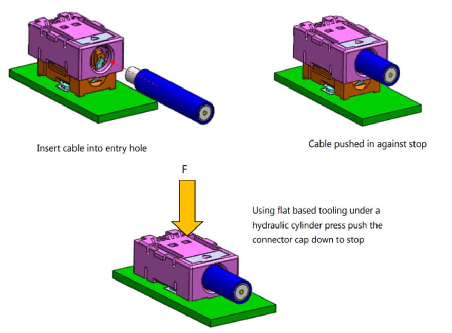
In production, the best method of pressing down the insulation displacement connector is with automated press equipment capable of pressing down at 320 N to 440 N to a precise distance. The actual press force for a given cable is dependent on the wire gauge, conductor strands, and insulation material. The pressed-down height of the connector should be less than 4.1 mm for the -001 version and less than 4.7 mm for the -003 version.
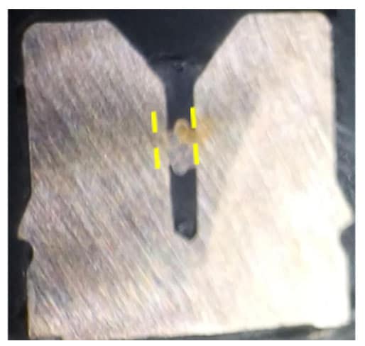
Figures 6 and 7 below show cross-section X-rays of the connector and cable after pressing. As long as all the designed tolerances are under control, the contact area should not be a concern.


Specifications
- Current Rating Continuous current rating @ 25°C ambient 0.5 Amps (Current limit is cable dependent)
- Voltage Rating 125V ac (rms)
- Dielectric Withstanding Voltage: 375V ac (rms), current leakage <5 mA
- Resistance Insulation resistance: 500 Megohms Min. Termination resistance: 30 milliohms Max, inner and outer RF Performance Typical figures measured on RG-174: VSWR less < 2.0 (Return loss > 10dB), DC – 6GHz Measurements taken with free wire ends terminated with SMA connectors
- Temperature Operating Temperature Range: -40°C to +85°C
- Storage Temperature Range: -40°C to +85°C, 50% RH Ambient Temperature: 25±2°C Humidity Level: MSL 3
- Vibration (Random) Contact Resistance: 10 mΩ Maximum (change from initial) Discontinuity < 1 microsecond
- Shock (Mechanical) Contact Resistance: 10 mΩ Maximum (change from initial) Discontinuity < 1 microsecond Thermal Shock Contact Resistance: 10 mΩ Maximum (change from initial) Visual: No Damage
Performance Measurement
Voltage Standing Wave Ratio (VSWR)
Compared to traditional hand welding procedures, the 6791 series connectors show excellent VSWR performance (<2). The improvement will depend on the type and quality of the coaxial cable used and following the specified assembly procedures for the connector.


Insertion and Return Losses
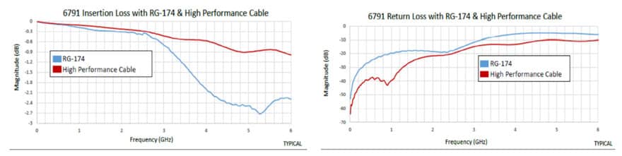
The 6791 series connectors contribute very low losses to a system from DC to 6 GHz. The insertion and return losses are presented in the following graphs and demonstrate high-performance cable performance versus a more standard RG-174 coaxial cable.

Benefits of IDC 6791 Connectors
The 6791 series of IDC connectors have many uniquely advantageous benefits to RF shark fin antenna applications. They are suited for solid or stranded wire, including coaxial RG174 cables, and provide gas-tight long-term reliability in automotive and other harsh industrial environments. The 6791 series is simple to use, assemble, costs less than Fakra or SMA connectors, and can be over-molded or potted.
Additionally, their assembly can be automated, improving consistency in production, quality, and RF performance versus traditional hand welding. Finally, they are low profile and can meet the demands of most shark fin antenna designs.
Conclusion
KYOCERA AVX’s new IDC 6791 series connectors will improve productivity, reliability, quality, and RF performance over traditional hand welding in shark fin antenna designs. Due to the capabilities of this connector to withstand harsh vibration and humidity environments while providing superior RF performance, shark fin antennas are a natural fit, but they will also offer the same benefits to many other applications.