Basic Principles
In an Ethernet network, all systems are connected to a single transmission line. There are some physical layouts, depending on the cable chosen and on the size of the whole LAN.
Today, token ring and ring are not so popular anymore and the mesh is certainly the most often used network configuration.
Protocols: 100BaseT & 1000BaseT
Communication in this network is achieved with the help of a protocol. IEEE provides different standards called 802.3xx protocols (xx depending on the speed). Nowadays, the most popular ones are Fast Ethernet (100BaseT) and Gigabit Ethernet (1000BaseT). For such speeds, a LAN network is built with a cat5 (or higher) cable with 4 pairs (Shielded or not). 100BaseT uses only 2 pairs while 1000BaseT needs 4 pairs.
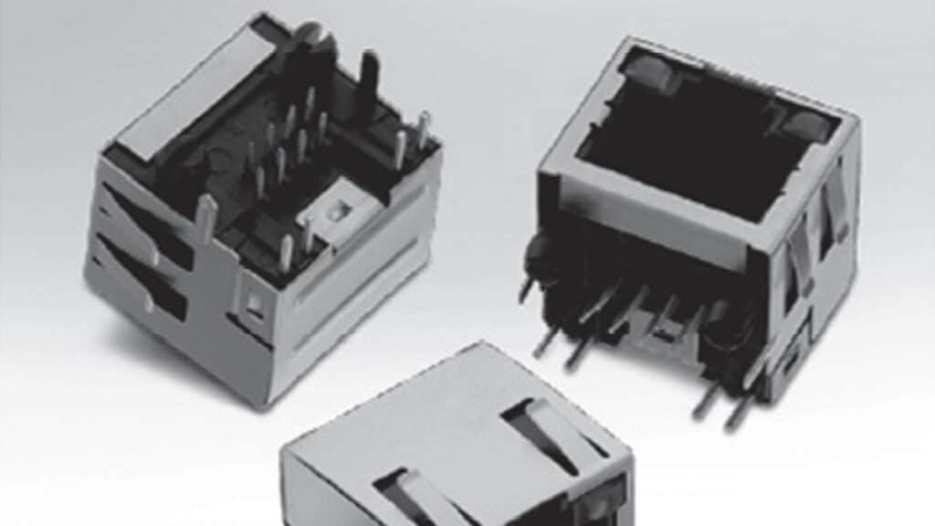
The 8P8C modular Jack (improperly called RJ45) is the first element of the Circuit Board Physical layer often named MDI (Medium Dependent Interface). This physical layer is controlled by an active device called the PHY. Further descriptions about the physical layer you can find in the design guide Trilogy of Magnetics.
Figure 2.155 shows the basic diagram of a physical layer for the 100BaseT.
As we can see on Figure 2.155, the pin assignment is pair 1-2 for TX and 3-6 for RX. Pairs 4-5 and 7-8 are not used for 100BaseT (but they are used for Gigabit).
The black box will be detailed later on.
Manufacturers of PHY (according to the Ethernet standard) enable visual control via mechanical means like LED or light pipes, giving the following information: Connection established, Tx, Rx, collisions, speed …
This option is useful within an ‘office’ type application in order to quickly check the online/offline status; it is even more useful with on-board applications. Therefore, it is not surprising to find modular jacks with several LED options.
A wide range of products is offered to designers to help them select the right Modular Jack for their applications.
This range consists in a single or multi-port (stacked or not), with tab up or down, shielded or unshielded, EMI fingers and with or without LED.
Single versions are also available in horizontal or vertical positions in SMT or THT PCB board mount.
What about Insulation?
As explained before, the modular jack is the first element of a physical layer, just between the cable and the electronic board. According to the specifications of the Ethernet standard (802.3), it is necessary to withstand 1500 Vrms 1min between port and chassis ground.
A transformer can easily do the job (it’s the cheapest solution) and help to meet this requirement; the question of having it integrated or not will be discussed later in this chapter.
EMI Reduction: What for?
High speed signal transmission is really sensitive to noise. Noise can easily be generated by the cable and create EMI (Electromagnetic Interferences). On an Ethernet port, noise is often coming in common mode. The best solution to attenuate it without damaging the signal is to use a common mode choke. This is why we always find a transformer and a common mode choke together (the black box described before). This set of components is called a LAN transformer.
Note: Resistors 4 x 75 Ω together with the capacitor on the bottom right side, form a so called “Bob Smith Termination” used to reduce EMI.
Discrete or Integrated Filtering Solution?
Now is the time to answer the question which arose a bit earlier in this article: “Shall we integrate the LAN Transformer in the connector or should we keep a discrete solution?”
Advantages of integrated solutions are the disadvantages for discrete solutions and vice versa … A designer makes his own decision, he has to balance these parameters against each other.
Advantages of the integrated option
• Lower number of components (lower assembly cost).
• Smaller foot print.
Disadvantages of the integrated option
• Harder to rework if a component fail during test (Higher production cost).
• Smaller size could increase coupling and therefore reduce the common mode effect.
Basically, there is no clear answer to this question, both solutions have advantages and disadvantages. It is not a trivial choice and each application will need to be considered on an individual basis.
Consequences of High Frequency on the Connector Design
The trend for high speed does not only imply changes for filtered connectors but also for the non-filtered ones.
Connector manufacturers created special cat5 connectors with a different pinning, where pin 1/2 and 4/5 have been shifted to compensate potential delays and to make it easier to remain below the maximum 45ns delay skew (see Table 2.14) allowed by EIA.
Basically, any cat5 connector can potentially fit for a cat5e application but the design below makes it easier to comply with the EIA standard.
It’s even more complex when it comes to higher frequencies like in the cat6 area. In this case we often find connectors with integrated capacitors (mounted on a PCB integrated in the connector) on every line to create a filter that reduces the noise at the entry level of the circuit.
