
Levels of Interconnection addresses where the connector is used within an electronic system. The location of the connector in the system influences the environmental exposure and the assembly/mating durability requirements the connector must support. These factors, in turn influence the type of connector which will be used at a given system level. It should be noted that more than one type of connector may be used at some of the levels.
The Levels of Interconnection, LOI, system for characterizing interconnect devices, primarily connectors, in electronic systems was first developed around 1990. That is multiple generations ago in terms of the functionality of electronic devices and, therefore, the functional requirements on interconnect devices. Despite that fact, LOI has some benefits in terms of characterizing some of the most important connector performance requirements. This is because LOI focuses on the devices being interconnected and where they are in the electronic system and this focus highlights some important connector performance requirements. An overview of an early five level version of LOI follows. Due to the proliferation of devices and connectors since 1990, only selected examples will be discussed.


Level 0
IC Chip or Chip-to Package. This is a device level interconnect including the interconnects among the devices on the chip and the interconnects between the chip Input/Output leads and the lead frame or package. Level 0 has, obviously, seen the greatest amount of change since 1990 with the device count and functionality of IC chips having increased dramatically since that time. These interconnects are all permanent connections.
Level 1
Level 1 includes chip carrier and DIP socket interconnects to a Printed Wiring Board, PWB. Chip carrier styles, pin counts and pin densities have increased to keep pace with the increased functionality of the devices. These interconnects may be soldered or mechanical with the mechanical connections being permanent or separable. Separable connections would be used until device reliability was established so that soldered connections could be considered.
Level 2
Level 2 includes board-to-board interconnects within a functional unit, a sub-assembly. Daughterboard to motherboard interconnects are typical with both one-piece, card edge, and two-piece connector being used depending on density and reliability concerns. Two-piece connectors can realize higher density and provide higher reliability. These interconnects generally provide both permanent and separable connections, permanent to the individual boards and separable between the boards.
Level 3
Level 3 consists of interconnects between sub-assemblies within the equipment, e.g. power supply to system board and memory to CPU. A variety of interconnect types may be used at Level 3 including board-to-board and wire/cable-to-board. A number of subsystems may be interconnected at this level using different cable and connector configurations.
Level 4
Level 4 interconnections are between sub-assemblies and system Input/Output, I/O. A variety of connector systems are used at Level 4 because of the variety of I/O support required, i.e., power, video, audio, telecom etc. Level 4 is the first level at which the connectors, in this case the I/O connectors, are externally exposed.
Level 5
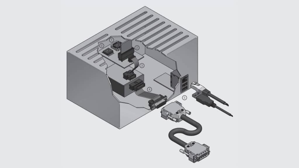
Level 5 consists of system-to-external system interconnects, the second half of I/O. These interconnects generally require an external cable assembly, e.g. printer-tosystem or data-to-system interconnects. The LOI approach can be applied to any system, although all levels may not exist in every system. Some connector families can be used at different level, that’s the example of the DSub connectors which can be used at level 4 as well as level 5 (see Figure 2.122) Consider now how these Levels impact on connector requirements such as robustness, environmental stability, mating force and mating durability.
Robustness
Robustness refers to the ability of the connector system to withstand improper handling and assembly. Levels 1 through 4 are internal to the system and, in most cases, are handled primarily by personnel trained in the proper treatment of the connectors. This does not mean that robustness is not a concern, however, because in some cases access to the connector may be awkward making the mating process problematic. Level 5 connectors are accessible to all users and subject to improper mating/unmating and unintended external loads. To address these issues Level 5 connectors often include polarizing and lead-in features to minimize the potential for mismating and strain relief to minimize the potential for damage due to unmating and external loading.
The D shape of the DSub connectors is certainly one of the most famous examples of connector polarization.
Environmental Stability
Corrosion, thermal and mechanical effects must be considered. With respect to corrosion, Levels 1 through 4 are shielded from the external environment by the enclosure. Keep in mind, however, that cooling fans may bring the external environment into the enclosure. There are two thermal effects to be considered since the temperature internal to the enclosure may be elevated above ambient by heat generating devices within the system, i.e. Joule heating and/or transformers. All connector degradation mechanisms, in particular corrosion and stress relaxation, increase with increasing temperature. Temperature differences, for example due to on/off cycling of the system may make thermal expansion mismatch a concern, especially for tin finished connectors due to the potential for fretting corrosion degradation. Mechanical stresses such as vibration can also create a driving force for contact interface motion leading to fretting corrosion in tin finished connectors and fretting wear, and loss of the gold surface, in noble metal finished contacts.
Mating force can be an issue in two ways at all levels. If, as noted above, the mating process is awkward due to the location of the connector in the enclosure, the potential for mating damage will be increased if mating forces are high. If the pin counts of the connectors are high this tendency will be increased. This potential negative, however, must be balanced against the mechanical stability that might be lost if mating force is reduced leading to motion induced degradation mechanisms as discussed elsewhere.
Mating durability is generally not a concern at Levels 1 through 3. It may be an issue at Levels 4 and 5 where the number of mating cycles could be high in the case of multi-use or portable equipment such as laptop computers where all I/O will be subjected to multiple mating cycles.