Modular Connector is the name given to a family of electrical connectors originally used in telephone and Ethernet wiring. Due to the fast development of this connector family, its use is not only limited to telecommunication anymore; it is now used for many other purposes.
Historically, Modular connectors were patented by Bell Telephone Laboratory and they replaced hard wiring in the mid-seventies.
Gender
Modular connectors are available in a male version named Plugs and in a female version named Jacks. The plug is used for the cable termination while the jack is used on fixed locations such as Electronic boards (PCB).
Latching
They are designed to latch securely plug and jacks together thanks to a “tab” which snaps into the jack when connected, so that the plug cannot be pulled out. To be able to unplug, the tab must be pushed down/up while pulling on the plug.
The most common way to install a jack, is to do it with the tab down; this makes it easier to operate (with thumb on top & index on tab). It’s also better because dust will tend to fall down instead of stacking on the contact area (tab down means contact up!)
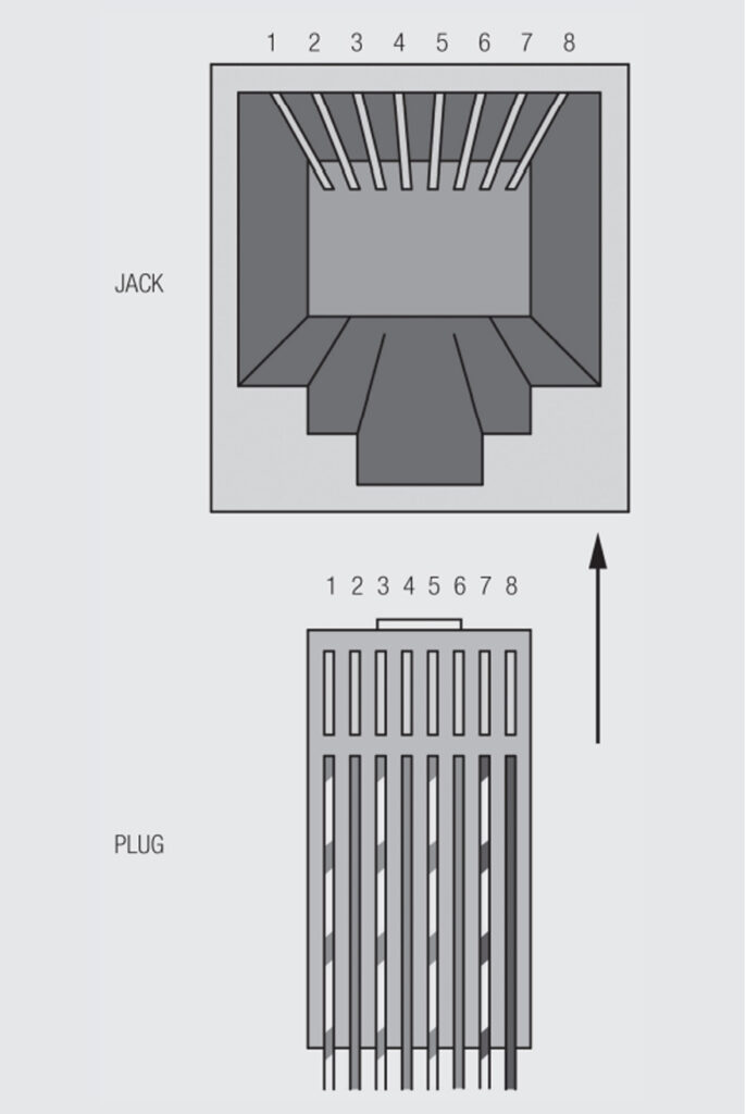
Pinning
With the tab down in front of you, you can count 1 to … from left to right (see Figure 2.147). A tab up configuration implies an opposite way of counting (from right to left)

Size and Contacts
4P and 6P plugs share the same plastic body while 8P and 10P share a larger one. There are different combinations in terms of number of positions and number of contacts. They can be described in 2 ways, the first one being xPxC.
Number of possible positions: 4, 6, 8, 10. It defines the number of possible locations for a contact.
Number of possible contacts: 2, 4, 6, 8,10. This figure stands for the number of possible electrical contacts.
For instance 8P8C stands for 8 positions, filled with 8 contacts (no empty pole).
The other option to describe these connectors is to use a Registered Jack (RJ) number. It is a standard to name network interface wiring and jacks. A few examples are RJ-11, RJ45, RJ21, RJ28 …
Let’s review the most popular configurations:
4P4C
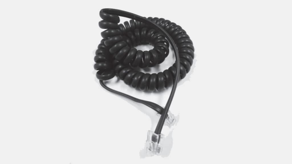
The 4P4C connector is popularly but incorrectly called RJ9. This is not correct because this connector is not an official connector/jack since registered connectors only classify the connection between different phones, or a phone and a network, and not between 2 parts of a phone as it is often the case here. Indeed, this connector is also called the handset connector since its most common use is to plug the telephone handset to the receiver. See Figure 2.148.

6PxC
6P2C = RJ11 is certainly the most familiar registered jack since it is used for single line telephone jacks in most homes across the world.
6P4C = RJ14 is similar but for 2 lines and 6P6C is for 3.
The most common configuration of Jacks is 6P4C but often only connected to a 6P2C cable (RJ11 cable).
8P8C
8P8C connectors are generally used for Ethernet applications.
Even if they are popularly called RJ45 in the context of Ethernet and cat5 cables, it’s not correct to identify 8P8C connectors as RJ45. In telephone systems, a standard RJ45S socket has a key which excludes insertion of a standard 8P8C plug. However, the unkeyed 8P8C version has spread so widely thanks to the computer market that the name RJ45 often designates the 8P8C without keying (which is not its original/official definition).
8P8C jacks support a physical connection with RJ11/RJ14 & RJ25 plugs but only RJ11 and RJ14 have full electrical compatibility. Ethernet compatible pinout split the third pair of RJ25 into two separate cable pairs making it unusable by similar phones (it was necessary to preserve the signal integrity for Ethernet which operates at much higher frequencies than telephone lines).
10P10C
The 10P10C connector is commonly referred to as the RJ50 connector although it’s not a standard registered jack. It has 10 positions fitted with 10 contacts. It is mainly used in proprietary data transfer systems; therefore, we do not find it quite often, except in special applications.
Termination IDC Technology
One of the main reasons for the success of modular jacks/plugs is the easy way to perform a cable assembly. Wires are presented into the plug as shown below and then pressed with a crimping tool. The sharp edge of the contact will perform a so called IDC termination (insulation displacement).
This can either be performed with a cheap hand tool or with an efficient automatic tool for higher volumes.
