
This article written by Steven Keeping, DigiKey discuss selection guide of RF connectors and How to optimize RF connector choices and implementation for military applications.
RF coaxial connectors and cables are common components that perform a largely unseen but highly critical role in military applications. The assembly’s job is to transmit RF signals—up to frequencies of tens of gigahertz (GHz)—from an antenna to a receiver. It must reliably handle and maintain the integrity of sensitive RF signals while being robust enough to potentially withstand the rigors of the battlefield.
There are hundreds of options for the engineer looking for an RF connector, and it can be tempting to choose the least expensive on the premise that RF connectors are more or less the same once they meet some basic requirements. That would be a mistake. Many RF connectors are not built to exacting engineering specifications, and failure of a poorly designed part can cause multimillion-dollar military hardware to be out of action at a critical moment. That makes it vital that the selected components are built to accepted international standards.
In addition to mechanical properties such as durability, moisture, and dust resistance, and electrical properties such as impedance, frequency range, voltage standing wave ratio (VSWR), and insulation resistance, other factors can make or break the design. For example, in certain military applications, such as rocket launcher rails, interior surfaces of optical parts, and small arms applications, light reflection from standard stainless steel connectors can cause operational problems.
Turning to a reputable manufacturer who demonstrates their RF connectors are manufactured to relevant military performance specifications and standards is a good place to start when looking for a robust and reliable RF connector.
This article considers the key electrical and mechanical selection criteria for RF coaxial connectors for military applications. It provides real-world examples from Amphenol SV Microwave and discusses their application. Particular emphasis is put on the use of a high-grade, durable, non-reflective finish for niche applications using black chrome RF connectors.

High-performance RF coaxial cables and connectors
The key to ensuring that RF components are up to the rigors of military applications is to buy components that comply with the relevant military performance specification (MIL-PRF). Only a select group of manufacturers can supply RF connectors that conform. One company that makes the grade is Amphenol SV Microwave. The company offers over 400 RF connectors that comply with MIL-PRF M39012.
MIL-PRF-39012 is the key standard for RF connectors. It demands visual, mechanical, and electrical testing at several manufacturing stages to ensure compliance. The specification also requires that manufacturing facilities and processes meet quality standards. Coaxial connectors and adapters that meet MIL-PRF-39012 are well-suited to military (and other high-reliability) applications, including radar, SATCOM ground equipment, and aerospace RF/microwave assemblies.
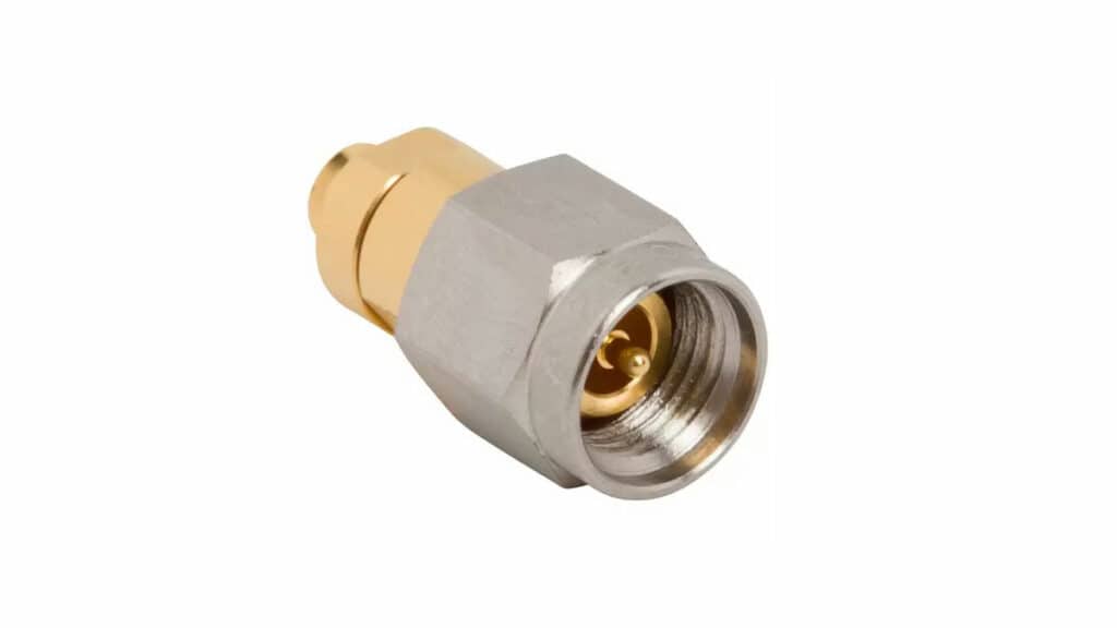
A key criterion of MIL-PRF-39012 connectors is that the center pin must be gold-plated to a standardized depth, adhesion quality, and finish. The gold plating on the captivated contacts ensures a minimum insertion loss and good electrical contact over long periods in tough environments (Figure 1).
RF coaxial cable design considerations
When designing RF coaxial solutions for military applications, it’s important to consider the cable and connector as a complete system. The performance of that system is highly reliant on the two components working in perfect harmony.

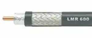
A typical coaxial cable comprises a core of copper or copper-coated steel wire. The core carries the high-frequency input/output signals to/from the connected equipment. A dielectric insulator, often made of plastic, surrounds the core. The insulator is of a constant thickness and ensures the gap between the core and the metal shield surrounding the dielectric is kept constant. This is important because any variation in thickness causes variation in impedance with a subsequent impact on signal integrity.
The metal shield is made of woven copper, aluminum, or other metals, and wraps tightly around the insulator. Its job is to shield the inner core from external electromagnetic interference (EMI). The assembly is then sheathed in a rubber or plastic jacket to insulate and protect the inner conductors (Figure 2). Outdoor-rated cables need extra insulation and special jackets to protect the wires from sun and moisture.
The inner core transmits the high-frequency signal while the shielding acts solely as a return line. An electromagnetic field exists between the two conductors but does not extend beyond the shield. This means that the RF signal traveling through the cable won’t affect nearby electrical and electronic equipment.
Where the dielectric insulator touches the center conductor, it absorbs some of the electrical energy. For long cable runs, the signal attenuation can be significant. High-efficiency cables use spacers that make minimal contact with the inner conductor and form a consistent air gap between inner and outer conductors that acts as an efficient dielectric.
The importance of impedance
In high-frequency RF systems, transmission efficiency relies on matching the impedance of the antenna with that of the transmitter or receiver.
Significant mismatch results in poor antenna efficacy because it interferes with the forward traveling power and creates a standing voltage wave. A common measure of how well the impedance is equalized is the voltage standing wave ratio (VSWR). A VSWR of 1 indicates no impedance mismatch loss, while higher numbers indicate increasing losses. For example, a VSWR of 3.0 indicates about 25 percent of the transmitter power is lost in the antenna system.
The RF connector and cable form part of the antenna impedance, so it is important the designer knows the impedance value of the components to maximize the efficiency of the RF system. The characteristic impedance of a coaxial cable is proportional to the ratio of the outside diameter of the inner conductor to the inside diameter of the outer conductor. The main function of the dielectric insulator is to set and maintain this separation.
In most cases, cable manufacturers supply RF cables with impedances of 50, 75, or 95 ohms (Ω), although other impedances are available. In addition to a range of fixed impedances, cables are supplied with different dielectric types, capacitances, outside diameters, attenuation characteristics, and shielding materials.
Versions are generally classified under two systems, LMR (the meaning of the letters is historical: the important thing to know is that these cables are a low loss type) and radio guide (RG). The RG type has a greater number of options, however, not all of them meet military specifications. A reputable supplier can assist with the selection for military applications.
RF coaxial connector considerations
The RF coaxial connector allows the cable to be securely attached to the radio equipment. No matter how good the cable is, a poorly fitted connector will undermine electrical performance. A mechanically secure and electrically robust mating between cable and connector will ensure good signal integrity and consistent impedance, even at high frequencies. One way to provide integrity is to specify the cable and connector together and have them delivered from the manufacturer as a complete assembly. The manufacturer is best equipped to ensure a high-quality connection and will also test the assembly’s integrity before delivery.
Standard polarized male connectors have threads on the inside of the shell and a center pin, while standard polarized female connectors have threads on the inside of the shell and no center pin. It is not good design practice to join cables together by mating a male with a female connector, as this will add to the cable’s inherent signal loss. It is better practice to specify a continuous cable for long runs as this will ensure lower signal loss and consistent impedance. The correct way to connect a male connector to another male, or a female to a female, is with a coax cable adapter. This will work, but in high-spec applications is not recommended as it will also increase signal loss.
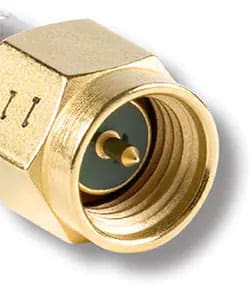
Like the cables, RF connectors come in various types and with fixed impedance values. A common example is the Subminiature Version A (SMA). The connectors feature a robust screw-type coupling mechanism, have a standard impedance of 50 Ω, and are designed for use from DC (0 Hertz (Hz)) to 18 GHz. Applications include microwave systems and handheld radios (Figure 3).
Non-reflective RF connector options
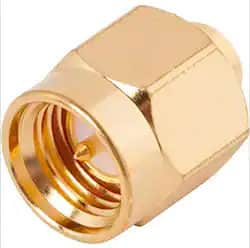
Reputable manufacturers offer a range of straight, angled, and male and female connectors. But some, such as Amphenol SV Microwave, also include specialty components among their offering. A key addition to the company’s range is a non-reflective SMA RF connector for both cable and bulkhead applications (Figure 4.).
There are many military applications where the standard stainless steel or brass finish of industrial RF connectors could cause problems. For example, if used on small arms, such RF connectors could reflect natural light and reveal a combatant’s position. Or RF connectors used in the optics of an aircraft or helicopter could generate light artifacts that undermine the precision of a targeting system.


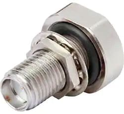
To meet the demand for non-reflective RF connectors, Amphenol has introduced a black chrome SMA male cable connector, the 2911-61008 (Figure 5 (left)), and a companion black chrome SMA female bulkhead connector, the 2921-61689 (Figure 5 (right)). The products feature an impedance of 50 Ω, and can support RF signals up to 18 GHz with up to 500 connection cycles. The center contact in each case is gold-plated beryllium copper. The RF connectors are designed to be used with RG-405 (0.085 inch (in.), semi-rigid RF coaxial cable, a type that complies with military specifications and is popular in defense applications.

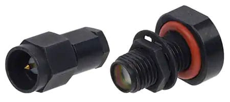
The RF connectors’ body material is stainless steel, to which has been applied a black chromium plate that meets the MIL-C-14538 standard. The black chromium plate covered by this specification is unique to the military and is hard, adherent, heat resistant, and completely non-reflective. The connectors are supported by a non-reflective SMA male dust cap, the 2911-61009, for use with the female bulkhead connector when the cable is disconnected.
Conclusion
Military applications are subject to dust, grease, heat, and vibration. Connectors and cables for these applications are expected to reliably transmit high-frequency signals over periods of many years. Variants of these connectors need non-reflective coatings that are tough and durable enough to withstand heat and impacts without chipping or wearing.
Designers of RF military applications can ensure their designs meet the needed requirements by turning to suppliers, such as Amphenol SV Microwave, which offer products complying with military performance specifications and standards.