

his article is an excerpt from ESA SPCD paper entitled “Resistive and Wilkinson Power Splitters at Frequencies of Millimeter Waves for Space Applications” written by Mo Hasanovic and Juan G. Ayala, Smiths Interconnect Americas presented during the 4th ESA SPCD conference at ESA ESTEC, The Netherlands 11-14th October 2022. Published under ESA SPCD organisation committee permission.

INTRODUCTION
Power splitters are passive radio frequency (RF) components that are used to split and distribute an input signal into two or more signals in various proportions to different components in a larger RF system.
These components have played a prominent role in RF systems for many years. Two of the main applications for power splitters are (1) distribution of input power to amplifiers and (2) distribution of a RF signal to antenna arrays. In the amplifier application, a power divider splits the signal to feed multiple low-power amplifiers and then to recombine the signals from the amplifiers into a high-power output signal. In antenna array applications, power dividers are used within a phased antenna array system to feed multiple antenna elements at different amplitude and phase levels.
This RF structure enables electronic beam scanning as well as focusing the antenna beam on different directions as a function of the phase difference at individual antenna elements. There are many different types of power splitters reported and used in various RF applications. Resistive and Wilkinson types are among the most frequently used and integral components in many RF/microwave chains. The structure of these traditional passive components has been continuously changing to respond to new challenges in modern communication systems.
Current developments in fifth generation (5G) technology, Internet of Things (IoT), and Industry 4.0 require an efficient, affordable, and economically viable beamforming technology. For some of these applications, hybrid beamforming offers a practical trade-off between analog and digital options. It reduces the complexity of digital beamforming and improves the thermal management while maintaining a reasonable level of performance provided by the limited digital processing.
Two-stage beamforming employs digitally controlled RF chains, power splitters and analog phase shifters [1]. In this paper, we compare a few power splitter technologies that could be employed in hybrid beamforming and present some of the advantages and challenges of various mounting options and platforms. This paper also describes our efforts directed toward the miniaturization, compactness, and efficiency of the proposed high frequency splitters. The splitters
presented in this paper are of Wilkinson and resistive types and include both equal-split and unequal-split options that could be used as basic building blocks for more complex power-splitting needs.
Many modern radar and satellite systems require a low insertion loss performance of their integral parts to accommodate stringent loss budgets and long communication paths. To meet this design requirement, the beamformer is often realized using suspended airline technology that provides a low effective dielectric constant and consequently low insertion loss. Design of a power splitter in suspended airline technology brings its own unique challenges that includes different effective dielectric constants of the even mode and the odd mode. In this paper, we describe an elegant algorithm to overcome the issue of different phase velocities of the even and odd modes in a Wilkinson splitter design realized in a suspended stripline.
Resistive and Wilkinson Splitter – Basic Theory
A power divider (splitter) is an RF device that conveniently divides input power into multiple segments that appear at its output ports. A power divider may also be used to combine the power if the flow of the power is in the opposite direction. In its ideal form, a power divider is a perfectly-matched, reciprocal, and lossless RF device.
Resistive power dividers are usually implemented with the same impedance at all ports. Two of the main configurations for a resistive power divider, the “delta” and the “wye,” are shown in Fig 1. Resistors used in these simple RF devices provide a good impedance match at each of the three ports. However, the resistive structure introduces a significant loss that is one of the major disadvantages for this type of power splitter.

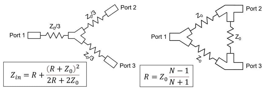
When designing a resistive power divider in a three-dimensional electromagnetic modeler and simulator, special attention must be given to the junction at the center of the structure.


This especially applies to high frequencies of millimeter waves where even small geometrical changes of order of 20μm may cause a significant impedance mismatch. The Wilkinson power divider, shown in Fig. 2, is an RF device capable of splitting the RF power in different ratios with all matched ports and excellent isolation between the output ports.
The design of the Wilkinson divider is composed of one or more quarter-wave transforming sections used to transform the impedance at the input port to the impedance at the output port. Based on the number of the quarter-wave sections, one can achieve good match at all ports in a desired frequency band. Resistors, connected at the junctions between individual quarter-wave transformers, enable good output return loss and isolation between the output ports. When the outputs are connected to matched loads for an equal-split Wilkinson, the voltages along each output transmission line are of the same magnitude and phase. This causes the connecting resistors to have no voltage drop across them, and consequently, dissipate no power [2].
Mounting Options for Surface Mount Components
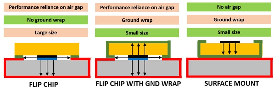
Power dividers may be realized on different planar platforms—microstrip, stripline, coplanar waveguide, etc. Each platform has its unique advantages and disadvantages. A microstrip platform provides for the simplest design and the most affordable manufacturing process as no bonding of multiple RF layers is required. However, the RF structure on a microstrip chip is isolated from the surrounding RF environment from one side only—the grounded one—and thus may be prone to undesired RF effects. A power divider on a microstrip chip may be designed in a few distinct configurations such as “flip chip,” “flip chip with the ground wrap,” and “true surface mount” (Fig. 3).

To compare the performance in different configurations, a few power dividers have been designed, manufactured, and tested. Board thickness, substrate (chip) thickness, and total thickness were measured using 5-digit micrometer.

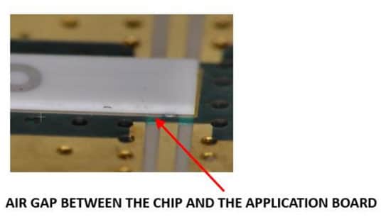
The conductor thickness was measured using a drop gauge on an unused blank board. It has been observed that the air gap thickness (Fig. 4) varies from 0 to 3 mil (0.076mm). This variation significantly affects the line impedances in the power divider structure. The air-filled gap between the chip and the application board caused by thicker-than-expected metal thickness adds undesirable inductive effect that affects VSWR and isolation.
As a result of this analysis, the surface mount option was selected as the most attractive one, both commercially and technologically, as it avoids reliance on specific application board properties as well as the variability of the air gap between the chip and the board.
Design of Resistive and Wilkinson Power Dividers for mmWaves
To properly support the introduction of new technologies at frequencies of K band, Ku band, and further towards millimeter wave, all aspects of component design and development must be considered—this includes high-frequency fixturing, high-frequency probing, and production testing. With the operational frequency increase, sizes of surface-mount chip components shrink while DUT-to-test-board air gaps become more critical. This and similar dimensional constraints create significant issues for a production test technician and therefore require serious consideration and analysis.
The physical length of the quarter-wave transformers is very short and often at the same order of scale as the corresponding line width at these incredibly high frequencies. The size of the resistive elements is electrically significant and introduces reflections that need to be properly tuned. Radiation effects become notable and must be properly addressed during the design of the power divider. A small misalignment during the mounting of the divider onto the application board may result in a significant amplitude and phase imbalance. Nevertheless, surface-mount resistive power dividers, if designed and mounted properly, provide for an excellent electrical performance and offer all the flexibility of a discrete component.
Designing a resistive or a Wilkinson power divider for millimeter waves has its own unique challenges. The physical length of the quarter-wave transformers is very short and often at the same order of scale as the corresponding line width at these incredibly high frequencies. The size of the resistive elements is electrically significant and introduces reflections that need to be properly tuned. Radiation effects become notable and must be properly addressed during the design of the power divider.
Finally, even a small misalignment during the mounting of the divider onto the application board may result in a significant amplitude and phase imbalance. Nevertheless, surface-mount resistive and Wilkinson power dividers, if designed and mounted properly, provide for an excellent electrical performance and offer all the flexibility of a discrete component.
The resistive 2-way power divider (Fig. 5) is designed on a standard alumina platform and offers a broadband performance that covers the entire range of frequencies from DC all the way up to 40 GHz. This component is optimized for a miniature size of 1.52 mm × 1.27 mm × 0.25 mm. Insertion loss of the resistive power divider is slightly below -6 dB, which means that half of the power is dissipated in the structure as expected. The return loss is better than -20 dB over the entire broad range of frequencies up to 40 GHz.

Basic structure of a 2-way resistive divider can be expanded into more complex structures with a higher order power split ratio such as 4-way, 8-way, etc. It is possible to customize the design for a specific size and position of input and the outputs.
Wilkinson splitters exhibit better insertion loss performance than resistive power dividers. However, since this type of power splitter relies on the quarter-wave impedance transformation, it is inherently a narrowband structure. To validate the proposed design procedure based on even- and odd-mode analysis, a few 2-way Wilkinson splitters with equal split ratio at Ka-band frequencies are designed, manufactured, and tested (Fig.6.). The splitters are characterized by –20 dB return loss, –20 dB isolation, and –0.5 dB insertion loss over the entire frequency bands of interest, 15–25 GHz and 25–35 GHz.

Wilkinson Divider in Suspended Airline Technology
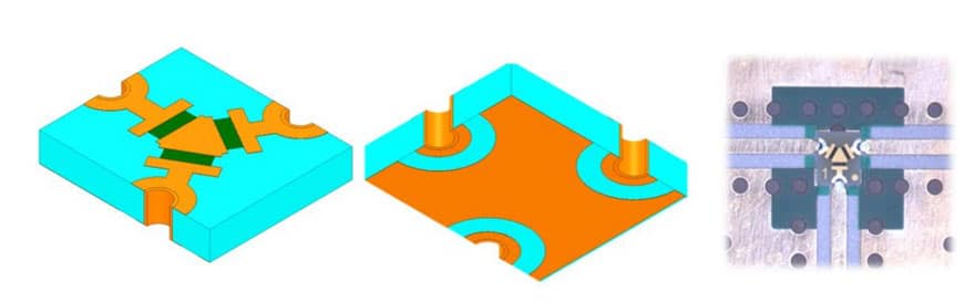
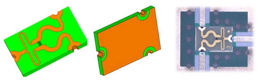
Modern radar and satellite systems often require a low insertion-loss performance of their integral parts to accommodate for a stringent loss budget and long communication paths. This restriction is imposed on the corresponding beamforming networks as well. To meet this design requirement, the beamformers are often realized in suspended airline technology (Fig. 7.) that provides for a low effective-dielectric constant and consequently low insertion loss.

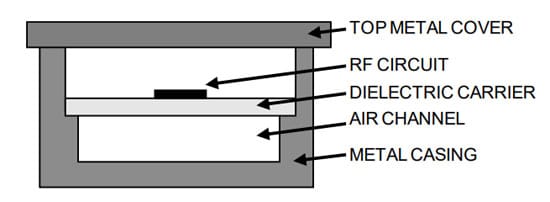
An important phase in the development of such a beamformer is the design of a corresponding Wilkinson power splitter [4]. If the splitter consists of coupled quarter-wave impedance transforming sections, then these sections would have different electrical lengths in even and odd modes due to different phase velocities of the two modes. This effect is further strengthened at the chip-resistor locations due to a high dielectric constant of the material the chips are built from (usually alumina, BeO, etc). Therefore, if the physical lengths of quarter-wave impedance transforming sections are tuned to be equal to quarter-wave lengths in even mode, the same physical lengths would not represent 90o sections in odd mode.
They would most probably be longer than 90o due to a higher dielectric constant of odd mode. This creates a design obstacle that is very difficult to overcome and results in poor functionality of the corresponding splitter. The problem of different lengths for even and odd modes has been treated by many authors in the past.
To solve the issue of different electrical lengths in even mode and odd mode, the quarter-wave transforming sections do not necessarily have to be separated by the shunt resistive elements, as is the case in the conventional Wilkinson power splitter [2], but instead pulled toward the T-junction. In even mode, this technique would still result in a traditional multisection quarter-wave transforming network optimized through the use of Chebyshev polynomials [7]. In odd mode, however, each transmission line section between the two consecutive shunt resistors will consist of two elements with different characteristic impedances but their electrical lengths would add up to a total of 90o.
The values of the shunt resistors then need to be optimized to satisfy matching conditions in a newly arisen odd mode transforming network [12]. This optimization is accomplished through an algorithm developed for this purpose and tested through multiple examples.
Proper Installation Practices
To avoid any potential electrical failures, the chip termination needs to be properly positioned (centered) and soldered in place. Introduction of the solder mask around the footprint area where the SMT chip is to be soldered helps this positional alignment. Surface mount installation (SMT) usually consists of chip (DUT) tinning, flux application to the test board, chip positioning (placement), and reflow.
Special care should be taken to ensure there is no solder run-out into the area where the chip is to be mounted. This is usually achieved by printing the solder paste directly onto the test board; if not possible, tinning the chip is the easiest way to control the amount of solder. If the chip is to be tinned, pay special attention to a uniform tinning on all pads of equal size and use mildly activated flux.
Conclusion
Power splitters will continue to play a major role in the RF power distribution systems. A large variety of different power splitter topologies addressing a specific requirement for a broadband, low insertion loss, or good match is proof of their popularity and extensive use in beamforming networks, RF amplifiers, and other RF applications.
In this paper, we presented a series of surface-mount resistive and Wilkinson power splitters at millimeter wave frequencies that could be easily deployed in various RF beamforming systems. Advantages and disadvantages of various mounting platforms have also been discussed with the conclusion that the surface-mount option provides the superior performance compared to the alternatives. Finally, we proposed a design technique for Wilkinson power splitters in suspended airline technology that provides a low insertion loss and thus is attractive for space applications.
REFERENCES
[1] M. A. B. Abbasi and V. Fusco, “Beamformer development challenges for 5G and beyond”, Antennas and Propagation for 5G and Beyond, pp. 265-299, https://doi.org/10.1049/PBTE093E_ch
[2] D. Pozar, Microwave Engineering, 3rd ed. Hoboken, New Jersey: John Wiley & Sons Inc. pp. 308-361, 2005.
[3] E. J. Wilkinson, “An n-way hybrid power divider”, IEEE Trans. Microwave Theory and Techniques, vol. 8, pp. 116–118, Jan. 1960.
[4] R. B. Ekinge, “A new method of synhesizing matched broadband TEM-mode three-ports”, IEEE Trans. Microwave Theory and Techniques, vol. 19, pp. 81–88, Jan. 1971.
[5] B. Deutschmann and A. F. Jacob, “Compact Ultra-Broadband Power Dividers with Integrated Resistors,” 2018 48th European Microwave Conference (EuMC), 2018, pp. 620-623, doi: 10.23919/EuMC.2018.8541600.
[6] V. Demir, D. A. Elsherbeni, D. Kajfez, and A. Z. Elsherbeni, “Efficient Wideband Power Divider for Planar Antenna Arrays,” ACES Journal, vol. 25, no. 10, October 2010.
[7] M. D. Abouzahra and K. C. Gupta, Hybrids and power dividers/combiners, Analysis and Design of Planar Microwave Components, IEEE Press, New York, 1994.
[8] S. L. March,, “Phase Velocity Compensation in Parallel-Coupled Microstrip”, 1982 MTT Symposium Digest, pp 410-412, June 1982.
[9] A. Podell, “A High Directivity Microstrip Coupler Technique”, 1970 MTT Symposium Digest, pp 33-36, May 1970.
[10]N. G. Alexopoulos and C. M. Krowne, “Characteristics of Single and Coupled Microstrips on Anisotropic Substrates”, IEEE Trans. Microwave Theory and Techniques, vol. 26, pp. 387–393, June 1978.
[11]D. D. Paolino, “MIC Overlay Coupler Design Using Spectral Domain Techniques”, IEEE Trans. Microwave Theory and Techniques, vol. 26, pp. 646–649, Sep. 1978.
[12] H. Y. Yee et. al., “N-way TEM-mode broadband power dividers”, IEEE Trans. Microwave Theory and Techniques vol. 18, pp. 682–688, Oct. 1970.