Now, let’s move on to the connector aspect in order to understand what this implies. Designing a brand new high-speed connector meeting the requirements is not an easy task, but adapting a more than 15 year-old existing one and making it high-speed capable while staying backward compatible is a really huge task.
The more specific requirements you add, like halogen-free plastic or special colour spec., the more complex it becomes to combine them together. Let’s have a look at all these parameters, both individually and in combination with the others.

USB Organisation Basic Connector Specs
The connector section (n °5/ so called mechanical) of the USB specification contains over 60 pages of mechanical and electrical details regarding the supposed properties of connectors and what they should be able to stand. These pages do not even describe the PCB foot print…only the mating face.
The stacked USB is not even described. Therefore, a huge space remains for interpretation and connectors based on customer requirements. Let’s review some of the key criteria like pinning … for the most important connectors.
The USB organisation specification defines the following connectors:
• USB 3.0 Standard A Plug and Receptacle
• USB 3.0 Standard B Plug and Receptacle
• USB 3.0 Powered B Plug and Receptacle
• USB 3.0 Micro B Plug and Receptacle
• USB 3.0 Micro A Plug
• USB 3.0 Micro AB Receptacle
We will review the most important ones, mentioned above in bold.
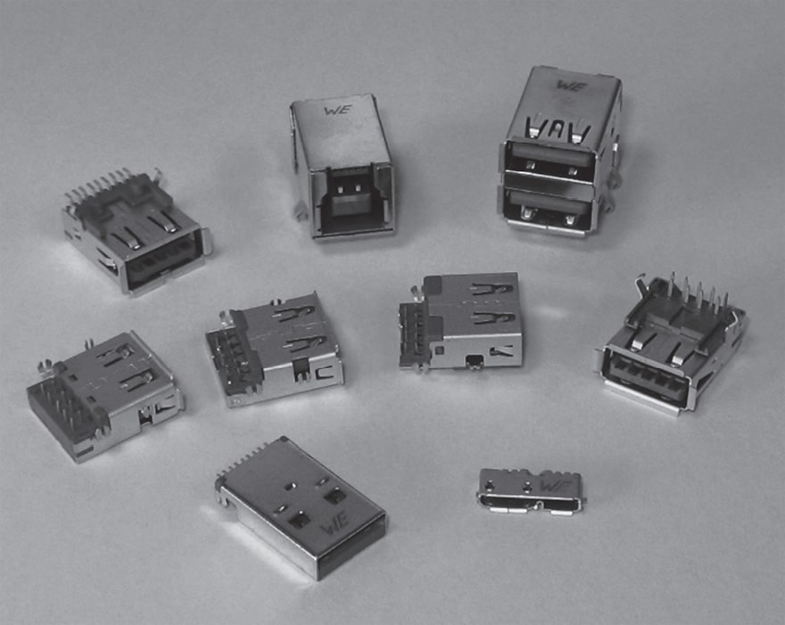
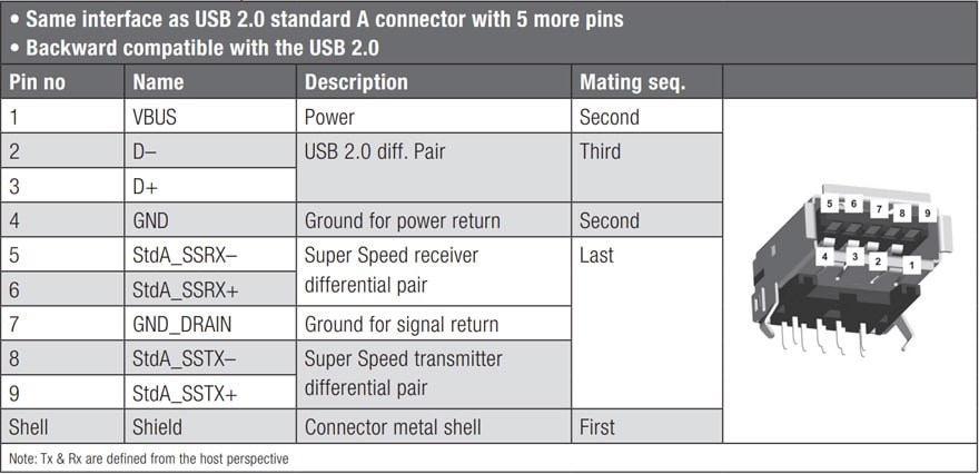
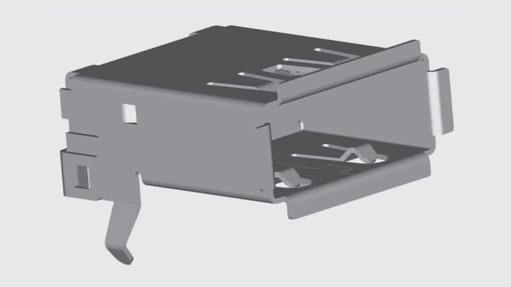
USB 3.0 Connector: A Type
The USB 3.0 Standard A connector is defined as the host connector, supporting the Super-Speed mode. It has the same mating interface as the USB 2.0 standard A connector, but additional pins for two more differential pairs and a drain.

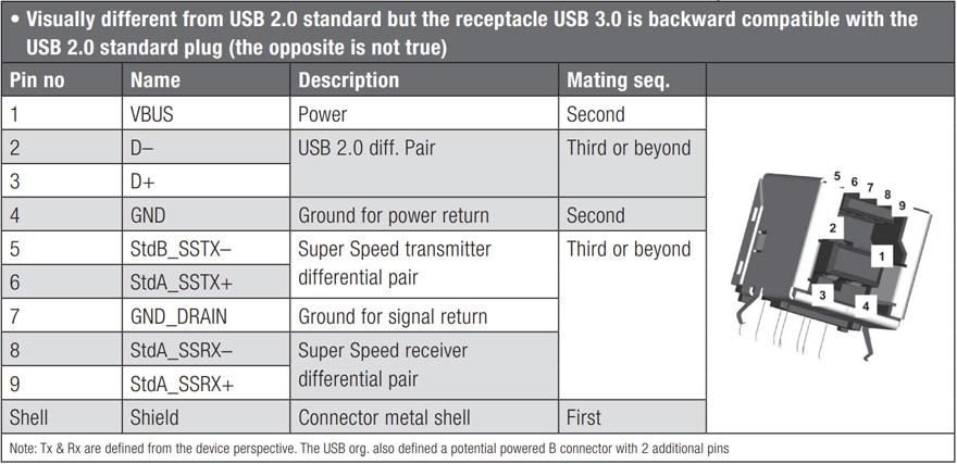
USB 3.0 Connector: B Type
The USB 3.0 Standard B connector is intended for relatively large, stationary peripherals, such as external hard drives and printers… It’s defined in such way that the USB 3.0 Standard B receptacle can accept either a USB 3.0 Standard B plug or a USB Standard B plug. Inserting a USB 3.0 Standard B plug into a USB 2.0 Standard B receptacle is physically impossible.

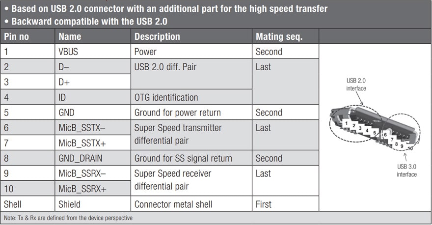
USB 3.0 Connector: Micro B Type
The USB 3.0 Micro B connector is defined for small handheld devices. It’s compatible with the USB 2.0 Micro B connector, i.e. a USB 2.0 Micro B plug works in a USB 3.0 Micro B receptacle. The USB 3.0 Micro B plug cannot be inserted into a USB 2.0 micro B receptacle.

Material Specs

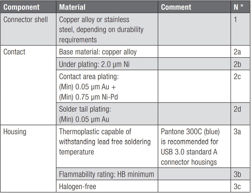
1) Shell (Table 2.10)
Both options are common for connectors and will not lead to major issues. Most important is to opt for a matt tin plating which enables much better solderability during the reflow process (compared to Ni plating). Only the plug should remain bright tin plated, since matt tin scratches easily (this could affect the visual aspect of USB sticks since the plug is not protected)

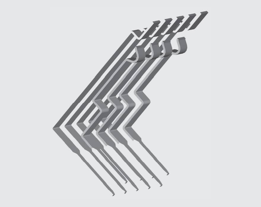
2) Contact
As described earlier in the text, the contact material for connectors is always a copper alloy but there is a huge difference between a phosphor bronze or a basic brass in terms of quality (and price obviously, see page 50/51).
A Ni under-plating layer is a must to guarantee a good plating quality. This recommendation is therefore to be followed.
Here we have a case of critical recommendation which had better not been followed. First of all, suppliers looking for a low cost option will go for a simple flash gold able to stand a minimum of 1500 cycles. This will certainly be much more critical than in the past for USB 2.0. What was possible for USB 2.0 with a lower data rate will become more difficult to implement since the signal tends to flow at the surface when the data rate increases. (Therefore, the impact of a non-stable plating surface like flash gold could become critical).
In this case, a 0.76 µm gold would certainly be the best option to enable the 5000 mating cycle together with a smooth data transmission.
The USB organisation recommends a 0.05 µm Au + 0.75 µm Ni-Pd which tends to be equivalent and slightly cheaper than 0.76 µm gold. This plating was popular in the 80’s when gold was really expensive but the Pd price has also increased a lot since that time. As a consequence this plating is not so common anymore. Although well handled by Japanese companies, this plating is not mastered by Chinese plating companies. As all suppliers will manufacture these connectors in China, it could be critical to follow the USB recommendations. This really small saving may not be worth the high quality risk that may follow.
A gold plating on the solder tail area is a nice option for whisker growth prevention but is not necessary since a good Ni under-plating with matt tin is sufficient for such a pitch (>1.5 µm).
Opting for gold on solder tail would lead to wettability issues since the gold plated contacts are always more complex to tin solder.
Here, we would rather go a for a standard selective plating with 0.76 µm gold on the mating side and tin on the solder tail.

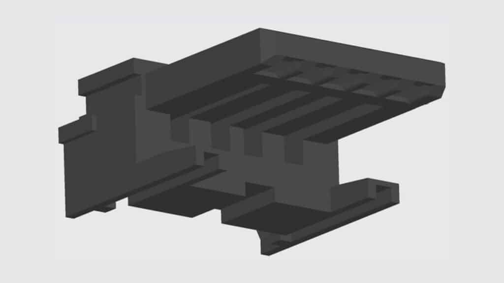
3) Housing
Here, not so many details even if this area is really critical.
Depending on the kind of lead-free we are talking about, whether wave or reflow, the impact on plastic selection is not the same. This will also impact the blue colour since the colour is likely to be affected during the reflow process (this will be illustrated later on).
HB rating is the lowest flammability rating in the UL range and comes after V2 and V0 which is the clear standard used for 99% of connectors sold on the electronic market.
It sounds really strange to state that the minimum rating required is HB rating, knowing that most customers request a V0 rating for safety reasons. Stating HB minimum is like mentioning that you expect a car with at least 4 wheels … as if anyone would ever think of requesting only 3 …!
Halogen-free is a trend in the electronic market and it’s an eco-friendly decision to recommend its use. Nevertheless, there can be a strong impact on the plastic housing selection, since halogen is a key additive used to ensure a good flammability rating. Maybe one reason for this low HB flammability rating seen just above?!

Combined Effects of these Material Requirements
Since both USB 2.0 and USB 3.0 may co-exist on a host, colour coding is recommended by the USB organisation to make it easier for users to differentiate the various ports.
Choosing to use the blue colour together with halogen-free plastic might seem trivial and the impact may not be obvious but this can have critical consequences.
We can already see that the USB organisation downgraded its recommendation to a low HB plastic flammability rating although this will hardly be accepted by end-product manufacturers who mainly request V0 plastic for their final products. Why going so low? Because halogen is the main additive used to make the plastic flame retardant. Without halogen, it is much more difficult to achieve a V0 rating.
As regards wave soldering, it remains possible to keep standard plastic like PBT or Nylon, to have them halogen-free and eventually even V0 rated. But when it comes to reflow soldering compatibility, everything becomes more complicated, especially because of the blue colour. Why?
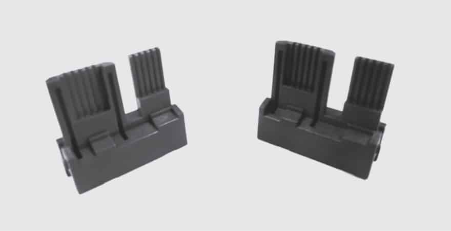
Consider Figure 2.140 below. On the left we can see the plastic insulator in its original blue pantone 300C colour. On the right side, we can observe the result after reflow:
the plastic turns into a horrible blue grey colour. Why? Because halogen-free flame retardant are not stable and react under heated conditions.
Combining UL 94V0 + blue colour + halogen-free + reflow is likely to produce such a result. Even if this doesn’t directly impact the connector function, it will be hard to find customers who are willing to accept such a horrible blue/grey colour on the side of their computer…

There are not thousands of options to combine the four parameters together: either you go for a PA46/6T or 9T plastic and decide to downgrade one of the parameters, or you go for LCP which is the only originally halogen-free plastic.
Knowing that the UL flammability rating is the only parameter you can downgrade to remain compliant with the USB recommendation (down to HB), there is a high risk that suppliers will offer this option to save costs. LCP is definitively the best choice if you aim to maintain the best quality possible.
USB Organisation: Connector Certification
While this chapter is written, only 3 laboratories worldwide are able to certify USB connectors. Two of them are located in the USA and one is located in Taiwan.
Whoever wants to have their connectors certified has to deal with one of these 3 labs to obtain one of the most wanted certificates in the field of connectors: the TID, Test Identifier Number which certifies that your connectors are officially approved.
Here, you must consider a cost ranging from US$ 20K to US$ 30 to have your connectors certified (depending on the generation 2.0 or 3.0). And even before that, you must be a member of the USB organisation (yearly membership of US$4K). This is quite a price to pay but this is certainly the only way to differentiate yourself from your competitors and to prove that your connectors comply with the USB IF spec.
A certified list of connectors can be found under www.usb.org/kcompliance/view