Board-To-Board connectors (BTB) were originally used primarily at Level 2. Recent developments have extended their application to Level 3. BTB connectors come in two styles, one-piece and two-piece. One-piece connectors were developed first with the two-piece style being developed as pin counts increased and centerlines decreased, that is for High-Density, HD, applications.
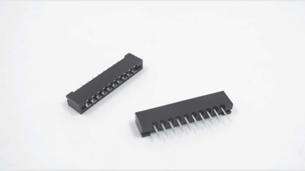
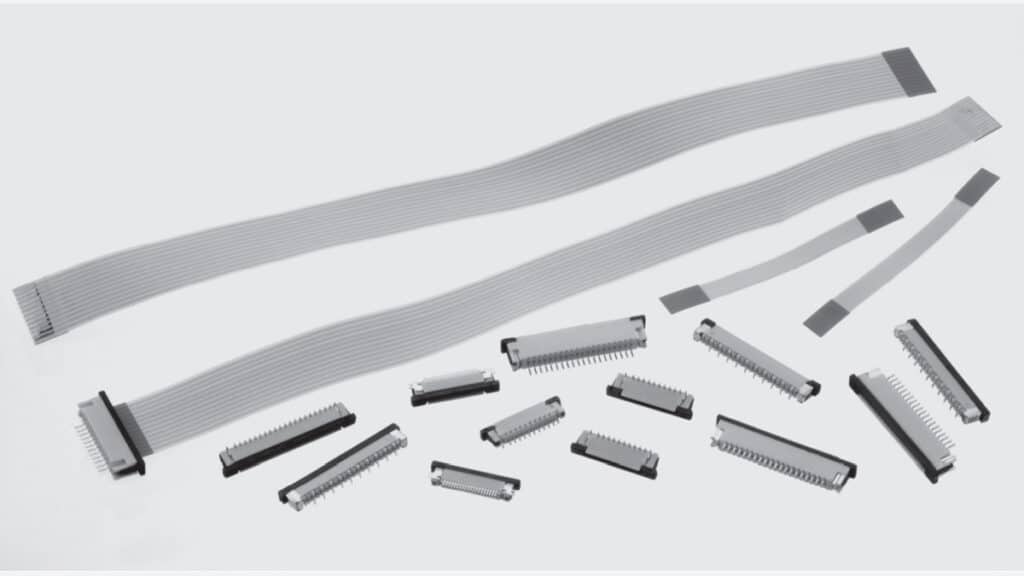
A one-piece system consists of a receptacle connector, mounted on the motherboard that accepts a daughterboard with contact pads on the edge of the PWB, hence the name “card edge” connector, Figure 2.125. The major advantage of one-piece connectors is cost; only a receptacle connector is needed. Limitations include the necessity to have contact pads on the board edge and, more importantly, tolerance control. The tolerance issues include variations in PWB thickness and bow or warp of the PWB, tolerances which vary with board size. Card edge connectors use one or two rows of cantilever beam contacts to mate to one or both sides of a PWB. The design of cantilever beam contacts must address these tolerance variations, which impact on contact force, in order to ensure meeting maximum and minimum contact force requirements. The minimum normal force requirement is intended to ensure mechanical stability of the separable interface. The maximum requirement addresses both connector mating force and durability concerns. One-piece BTB connectors are generally through hole mounted to the motherboard by soldering or compliant press-in connections. Contact springs are generally phosphor bronze with tin or gold over nickel finishes depending on the application. Connector housing materials include polyester, PPS and, for high pin counts, LCP. High pin count card edge connectors with Low or Zero Insertion Force, LIF/ZIF, designs have been developed.


Two-piece BTB connectors have superior tolerance control due to the control of separable interface tolerances available with stamped and formed contact in the receptacle and plug housings. This advantage, of course, comes at a cost. As noted, two-piece connectors were initially developed to address tolerance issues in high density connectors, but increasing electrical performance requirements and the proliferation of SMT applications have spurred further developments.
The advantages of two-piece BTB connectors with respect to HD applications are two fold. First, connectors with two to eight rows are possible, and, second, tighter centerlines can be realized (see a 0.8 mm itch example Figure 2.127).

The advantages of two-piece BTB connectors with respect to enhanced electrical performance are also two fold. First, ground pins can be assigned to enhance impedance control in open pin field connectors and, second, ground planes can be incorporated to introduce Microstrip and Stripline impedance control.
Two-piece BTB connectors are more suitable for SMT applications due to the reduced contact forces, and tolerances, and the reduced mating forces that can be realized, which is an important requirement for SMT.
The same materials noted for one-piece BTB connectors are used, with the addition of beryllium copper as a contact spring material option. Contact spring designs are also different in that post receptacle designs with two or four receptacle contact beams replace the single cantilever beams typical of card edge BTB. This design difference is, of course, the reason for all the advantages of two-piece BTB discussed. The most common two-piece configuration has the pin contact half of the system mounted on the motherboard which mates to a right angle receptacle contact mounted on the daughter card. The termination to the PWBs may be by either soldering or compliant press-in technologies.
BTB connector variants are also used at Level 3. In most Level 2 BTB applications the daughter card plugs into the motherboard vertically. In Level 3 BTB the daughter cards may plug into the motherboard horizontally using right angle BTB connectors. This configuration is often called a mezzanine connector, often seen in computer/Telecom applications.


