This KYOCERA AVX whitepaper by Ashok Dhulgande and John McCarry discusses key design considerations for electrical spring contacts and board connections and provides an overview of KYOCERA AVX’s card edge connectors for automotive applications.

Board-to-board Interconnect
It is often necessary to electrically connect two printed circuit boards (PCBs) directly to one another without using an intermediate collection of wires. A modular design constraint may drive this need — for example, an optional cellular connectivity system or by a form-factor requirement, such as a display that mounts perpendicular to a host processor board.
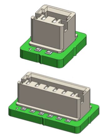
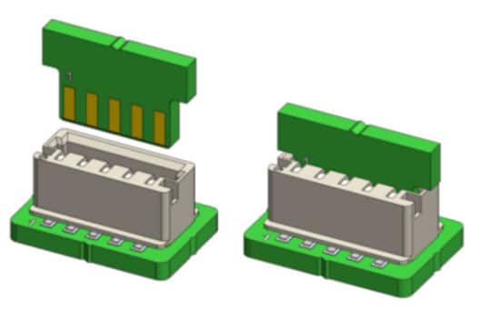
These board-to-board connections are generally divided into classes based on physical orientation and construction topology. Physical orientation is quite simple, and it is characterized as either stacking, perpendicular, or coplanar. Construction topology can be either two-piece mating connectors or a single connector that makes contact with conductive fingers patterned on the surface of a mating PCB. Several examples are shown in Figure 1.
Electrical Spring Contacts
In any aforementioned connection strategies, electrical contact is created using a spring force applied across two metals. The science of establishing and maintaining a high-quality electrical contact in this manner is quite complex, and it largely focuses on the microscopic qualities of the contact surfaces.

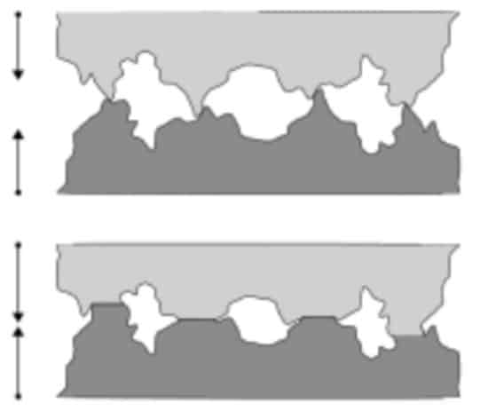
Even highly polished metals appear quite rough under high magnification, a quality often referred to as surface asperity. When they are brought into physical contact with each other, only the rough asperity spots (or “A-spots”) make an electrical connection. The electrical contact resistance can be minimized depending on the quality and the force applied across the two surfaces, as shown in figure 2.
The typical material composition for spring contacts is a high-performance copper alloy with gold over nickel plating. These springs are used for the highest reliability applications. If cost is more critical than reliability, tin plating is also used with
higher contact forces to avoid electrical resistance problems caused by fretting and corrosion.
In addition to the base materials used in the contact, the shape and size of the spring itself are critical to establishing a quality connection. The spring exerts the pressure force (known as normal force) to the mating contact. In the early days of spring technologies, normal contact forces were quite high, in the range of 200-300 g. Today’s designs are much more advanced and have reduced the required contact forces as low as 25 g. As such, physical wear and tear have been minimized while maintaining repeatable, high-quality connections.
Spring design geometry is a critical factor in contact performance: the spring must have the correct beam design to achieve the required contact forces and provide the spring deflection needed to function properly in the application. In addition, during contact engagement, all spring contacts create a small sliding movement with the mating contact.
This sliding action ensures the connection is clean and provides good electrical contact between spring contact and the mating surface. It is always recommended to design mating PCB pads with the same plating material as the spring surface i.e. gold plating over nickel undercoat.
Automotive Card Edge Solutions
KYOCERA AVX’s unique board-to-board right angle connection solutions have been utilized extensively and successfully in lighting and industrial applications. In recent years, this scope has broadened to include automotive interior electronics, such as sensors, light control modules, overhead control units, and HMI’s.
In particular, KYOCERA AVX’s top entry SMT 9159-550 series, one-piece card edge connector has gained popularity as a cost-effective and reliable alternative to the traditional two-piece BTB solution. Since many automotive applications require only a single mating cycle, this cost reduction and simplification has been a welcome progression.
The 9159-550 top mount configuration enables small perpendicular daughter cards to be plugged in from the top side of the mainboard without high insertion forces. The PCB board opening is dually slotted to accept either a 0. 8mm or 1.6 mm thick daughter card within the same connector body. Due to the nature of spring contacts, the mating force is lower than 5N per contact, and the specified separating force is greater than 0.5 N.


This connector comes with an insulator housing of high-performance Nylon UL94 V0 Halogen-free material, beryllium copper contacts with gold plating over nickel, and tin on tails for enhanced reliability. Beryllium copper is the best material for spring characteristics, price, durability, and fatigue resistance.
The contacts are placed at 2 mm pitch and provide a full 2A per contact current rating with a voltage rating of 300 Vac. These connectors are rated for 10 mating cycles, with an operating temperature between -40°C to + 125°C. It is worth noting that this card edge connector is also REACH, RoHS compliant, and carries UL certification.
The mating PCB pads should always be plated gold over nickel to give a reliable mating surface. In recent years, KYOCERA AVX has seen an increased demand for a higher pin count. KYOCERA AVX has designed a new 9159-650 dual-sided 6 to 12 position card edge connector, available in different configurations to meet that demand. Previously, the single side vertical card edge was limited to 2 to 6 positions.
Conclusion
Due to advancements in spring design and materials research, KYOCERA AVX’s board-to-board connectors have proven reliable and cost-effective in even the most challenging automotive environments. While the single-piece right angle connector above has already found favor in automotive interior applications, various
orientations and construction topologies are available to meet the needs of any application.
KYOCERA AVX Fine Pitch Two-Piece connectors provide multiple packaging solutions for perpendicular, parallel, and coplanar applications. Features include ultra-small pitch, low stacking heights, and a broad range of pin counts for various power and signal requirements.


