Thermal management and temperature derating have always been something that designers have had to plan for to keep their products safe. Temperature and power are closely linked, especially when it comes to connectors. This Samtec article discusses connector temperature and current rating challenges.
The Resistance
Every electrical circuit has resistance. The value may be small, but when passing power through that circuit, any resistance causes some of the energy to be converted into heat. With enough power, this can cause a rise in the temperature of the terminal, and therefore everything else around it.
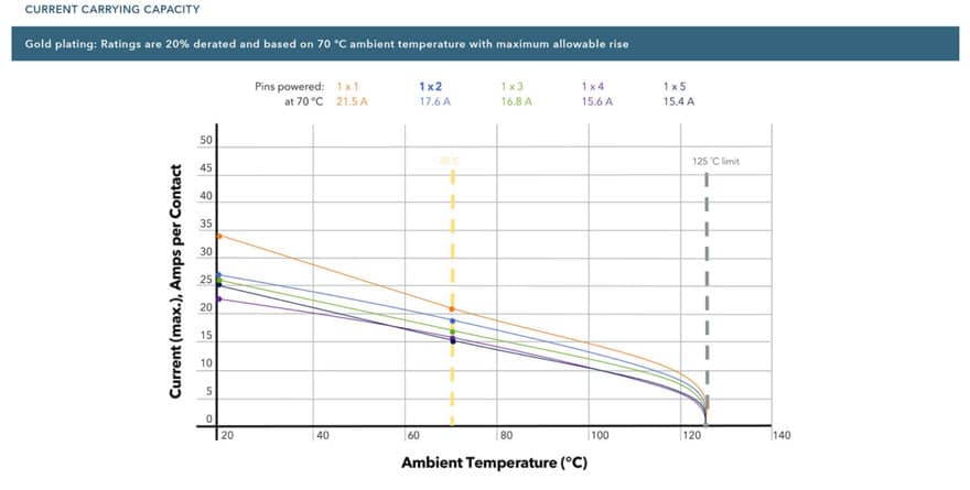
For this reason, it is important to understand how much heat is generated. In common with many connector manufacturers, In the example below Samtec publishes a temperature derating chart, in particular for power connectors. Here is an example, taken from the popular mPOWER® series of power connectors. This chart on Figure 1. shows the maximum power rating for contacts for a particular ambient temperature.

In the example on Figure 1. shown here, we can see that an ambient temperature of 70°C requires that we reduce the current passing through the contact by 20%. Placing this information into a hypothetical real-world installation, we can see that external conditions play an important role in the performance of connectors.
We also need to consider the published operating temperature of the connector itself. This will often be limited by the materials used in the connector’s design, in particular the plastic used for the insulator. In our hypothetical example, the operating temperature range of the connector might be 125°C, typical for a connector fitted with gold-plated contacts. There are also connector types with tin-plate contact finishes as a more cost-effective option. However, it is important to note that the operating temperature for tin-plated contacts is lower.
Solving the Temperature Problem
There are several solutions to the problem of temperature and current ratings. The simplest approach is to use a connector with larger contacts. One of the key factors governing the current rating of an electrical terminal is its mass. A larger terminal with more material should have a lower resistance and be able to carry more power. However, as we are trying to find solutions for the compact designs of the future, a larger connector is not always convenient.
Another way to solve the problem is to use a connector with a larger pitch. Pitch is the term used to describe the distance between terminals within electrical and electronic components. A greater pitch will aid in the dissipation of heat, which should lead to a reduced temperature rise for a given current. However, this is also will result in a larger connector, which does not solve our design problem.
The thoughtful approach is to consider the contacts themselves. Conventional designs comprise a fixed male contact that is inserted into a socket or female. The mating area of the female terminal is split or bifurcated, and the two parts provide a constant force to ensure electrical continuity. The actual area of contact between the two terminals is small. However, alternative contact designs allow greater performance.