After this discussion about the effects of contact normal force, attention now turns to the design and material parameters that determine contact force. The following discussion will focus on a cantilever beam (supported on only one end) contact design for simplicity, but the same general principles, appropriately modified, will apply to other beam designs.

Before considering the cantilever beam, however, a review of the stress-strain diagram is necessary to define some of the relevant parameters to be discussed. Figure 2.22 shows a representative stress-strain diagram obtained from a sample pulled in tension. The deflection of a contact beam occurs by bending, but the same parameters as noted in the tensile diagram apply to bending. The most important parameters in the diagram are:
- The elastic modulus, E, the slope of the stress-strain relationship in the region where that relationship is linear.
- The elastic limit is the maximum stress that can be applied without any permanent deformation. In the case of tensile loading, the elastic limit is the maximum stress the sample can support without increasing in length. In bending loading it is the maximum stress the sample can support without causing a permanent bend in the sample.
- The yield strength is the stress that causes a specified elongation of the tensile sample. The 0.2% offset is a commonly used criterion for specifying the yield strength of a metal. Using this criterion, the stress that causes a 0.1 cm increase in the length of a 5 cm tensile sample is the 0.2% offset yield strength.
- The strain, or elongation, is given by ΔL/L where ΔL is the change in length of the sample and L the original length of the sample.

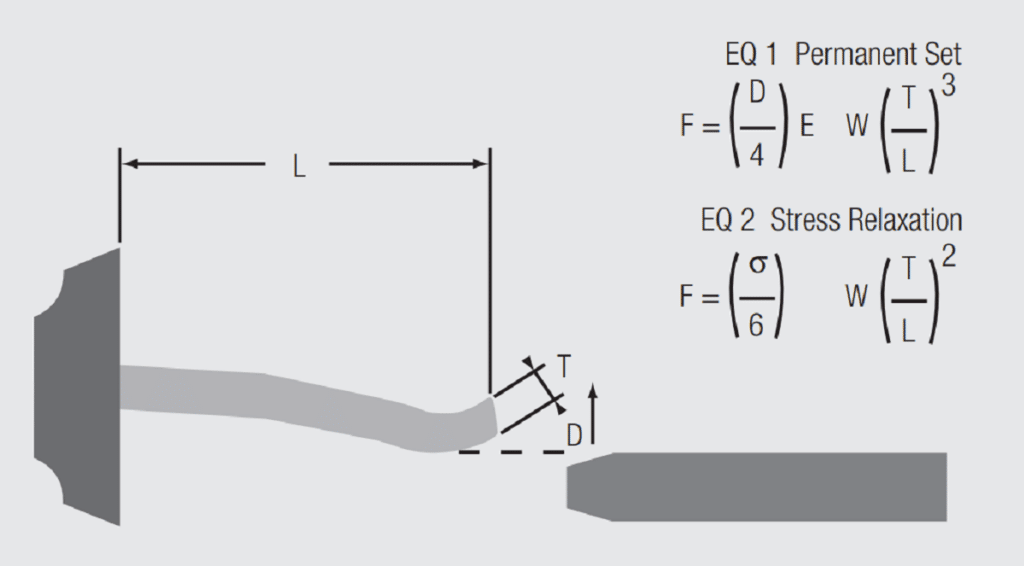
Figure 2.23 schematically illustrates a simple cantilever beam. The beam is fixed at one end and the maximum stress during deflection occurs at that end.
There are two equations for normal force in Figure 2.23. Equation 2.2 shows the relationship between contact force and receptacle contact beam geometry and deflection.


where F is the contact force, E is the elastic modulus of the base metal of the receptacle contact, D is the deflection of the receptacle contact beam by the plug contact, w, l and t are the width, length and thickness of the receptacle contact beam. Elastic modulus is a material parameter and varies with the contact material. The variation in elastic modulus over the typical range of copper alloys used in connectors is of the order of 110 to 140 kMPa (16–20 Mpsi). For example, consider three alloys used in connectors, brass (C26000), phosphor-bronze (C51000) and beryllium-copper (C17400) the elastic modulus of these materials is 110, 110 and 135 kMPa (16, 16 and 19 Mpsi) respectively. The beam deflection, D, is a design parameter. The contact beam geometry is also a design variable. For a given set of D, w, t, and l, and the limited range of elastic modulus for copper alloys, cantilever beam contacts will give a contact normal force within a range of about 20 percent for the copper alloys typically used in connectors according to Equation 2.2. But that is not the whole story, as indicated in Equation 2.3 of Figure 2.23.

where σ is the stress introduced in the contact beam by the beam deflection, and w, t, and l, are as described above. The maximum stress a beam can support without plastic, or permanent, deformation is given by the elastic limit of the material. As mentioned previously, materials are generally specified in terms of the 0.2 percent offset yield strength, a value roughly proportional to the elastic limit. The commonly used yield strengths of the example materials in connectors are of the order of 45, 55 and 65 kMpa (65, 80 and 100 ksi) for brass, phosphor-bronze and beryllium-copper respectively. These data show that, for constant geometry, and quasi-elastic deformation, beryllium copper can support a higher stress, that is a higher beam deflection and, therefore, generate a higher contact force than phosphor bronze, which, in turn, can generate a higher contact force than brass.
Equation 2.2 suggests that contact forces will be stable for beam deflections that leave the beam in an elastic state. Beams stressed beyond their elastic range will be plastically deformed and, for a cantilever beam contact, take a permanent set. In the case of dual beam contact systems, such permanent set will be evidenced by an increase in the gap between the two beams when the connector is unmated. This increase in the gap between the beams will result in a lower overall beam deflection and a lower contact force when the contacts are remated. Overstressing of contact beams may occur during mating of the connector due to improper alignment during mating. Many connectors have anti-overstress features such as alignment features or beam stops to reduce the potential for contact force reduction due to permanent set.
Similarly, Equation 2.3 suggests that contact forces will be stable as long as the stress due to beam deflection remains stable. This may not be the case in practice due to stress relaxation. The metallurgical definition of stress relaxation is a time dependent decrease in stress at constant strain. For a connector this translates into a time dependent loss in contact force while mated. Stress relaxation, and the accompanying loss in contact force, is strongly temperature dependent. Figure 2.24 shows the loss in stress as a function of time for brass, phosphor bronze and beryllium copper alloys. Because Equation 2.3 shows that the contact force is proportional to the stress, the stress remaining axis could also represent the contact force remaining as a function of time at temperature. The designations on the right side of the figure identify the material and the temperature of exposure or heat aging. For example in the top three curves the brass and phosphor bronze were heat aged at 25 degrees Centigrade while the beryllium copper was heat aged at 105 degrees Centigrade.
The stress relaxation resistance of be-copper is significantly better than that of phosphore bronze or brass (be-copper shows less stress relaxation at a much higher aging temperature). The other two curves indicate that the stress relaxation resistance of phosphor bronze is superior to that of brass. Stress relaxation limits the temperature capabilities of copper alloy. Be-copper can be used in the temperature range of +125 ºC while recommended limit for phosphore bronze is +105 ºC. While stress relaxation may not be significant in many connector applications, below, say +55 ºC, it cannot be ignored at temperature above that value especially in power applications where Joule heating can increase the temperature of the contact spring up to 30 degrees above the application temperature.


To summarize, the contact normal force requirement for a connector is the force necessary to maintain mechanical stability of the contact interface under the stresses of the application environment. This value, typically in the range of several tens to a few hundred grams, is much larger than the force necessary to create a contact interface with an acceptable electrical resistance, a few milliohms.
The significance of the loss in contact force due to stress relaxation is due to the associated decrease in the friction force, which also means a decrease in the mechanical stability, of the contact interface. As noted previously, the mechanical stability of the contact interface is critical to preventing fretting motions and the effect of such motions on the corrosion susceptibility of the connector.
A second effect of stress relaxation is due to a change in the geometry of the contacts. Consider the cantilever beam contact of Figure 2.25.

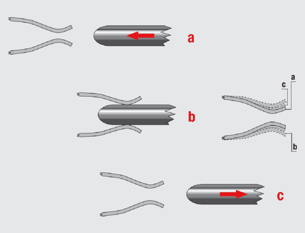
The drawing shows the original beam position, a, the deflected beam position, b, and the beam position on unmating the connector, c, after stress relaxation has taken place. The reason for the change in beam position is due to the kinetics of stress relaxation. Atomic motion occurs on a microscale to reduce the localized stresses of beam deflection. Consider a cantilever beam contact where the deflection stress is concentrated near the fastening point of the beam. The atomic motions at this point effectively reduce the residual elastic stress so that when the beam is unloaded, the connector is unmated, the beam does not return fully to its original position. This means that subsequent beam deflections on mating will be reduced compared to the original dimension and the resulting contact force will be lower than the original value.
If the stress relaxation is sufficiently large, the mechanical stability of the system may be compromised. This effect is analogous to the effect of overstressing and plastically deforming the contact beams due to pin misalignment or oversize pins.