Insulation Displacement Connectors (IDC) are used primarily on cables, in particular ribbon cables, in cable-to-cable or cable-to-board applications. Prior to IDC technology contacts were individually loaded into multiposition connectors by a process known as crimp-snap.
For, say a 60 position connector, the crimp-snap process required handling 60 individual wires, each intended for a specific position in the housing, stripping the insulation, crimping a contact onto the conductor and inserting the contact into the appropriate cavity in the connector housing.
In contrast using IDC technology a 60 conductor ribbon cable is oriented and inserted into a 60 position housing preloaded with IDC contacts and all of the conductors are terminated with a single stroke of the IDC tooling. IDC production rates are much higher given that a single cable is handled rather than 60 individual wires; no insulation stripping is required as compared to 60 individual insulation stripping operations; all conductors are terminated simultaneously rather than 60 individual crimping operations and the terminated IDC contacts are simultaneously inserted into the prehousings as compared to insertion of 60 individual crimped contacts into the appropriate cavity in the connector housing.
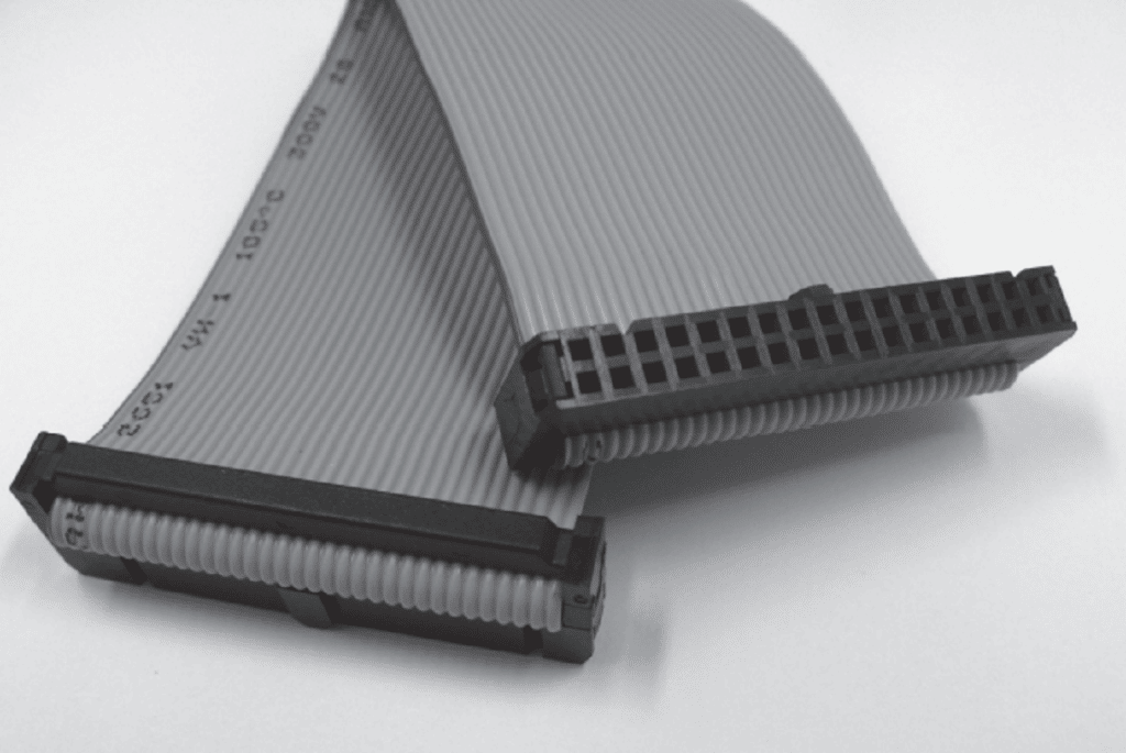
The improvement in production rates is obvious from Figure 2.56. But there is more. In the crimp-snap process the individual wires must be selected and inserted into the proper cavity in the housing – 60 opportunities to make a wiring error. In contrast, the ribbon cable needs only to be placed “right side up” into the preloaded connector housing to eliminate wiring errors. It is easy to understand why IDC technology dominates in cable-to-cable and cable-to – board applications


The Insulation Displacement Connection Process
IDC connections must meet the same requirements for permanent connections as crimped connections an acceptable and stable value of connection resistance. In other words an appropriate area of metal-to-metal; contact and a contact force system to ensure the integrity of the connection interface under the mechanical and thermal stresses of the application environment. The system for creating and maintaining the metal-to-metal contact interfaces is quite different from that of crimping.
Figure 2.57 schematically illustrates the insulation displacement process and the creation of the metal-to-metal contact interfaces in an IDC contact that has both an insulation displacement slot and an electrical contact slot. This design was chosen for ease of discussion and many IDC contacts have a single slot with a more gradual transition between the insulation displacement and electrical termination functions. Figure 2.57a shows the wire as it is being inserted into the insulation displacement portion of the IDC contact. In Figure 2.57b , the insulation has been displaced and the conductor is moving downward into the electrical contact portion of the IDC contact. In Figure 2.57c the conductor is at its final position in the contact slot. Figure 2.57d shows a cross section of the conductor at its final position in the contact slot. Consider the processes taking place at each position.

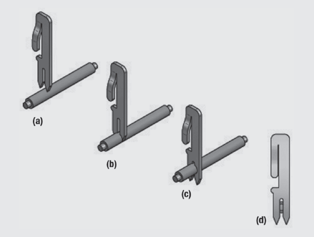
Figure 2.58a provides a more detailed schematic view of the insulation displacement process. The width of the gap in the insulation displacement slot is wire size dependent and is intended to compress the insulation and create friction forces between the insulation and the sides of the slot. The ramp angle and roughness of the slot can significantly influence these friction forces. In addition, some slot designs coin edges, along the ramp, or create edges at the ends of the ramp to initiate the separation of the insulation from the conductor. There are two reasons why complete displacement of the insulation is important. First, electrical contact, as noted, requires metal-tometal interfaces. Second, if insulation is carried into the electrical portion of the IDC slot it can compromise the contact force as will be discussed.

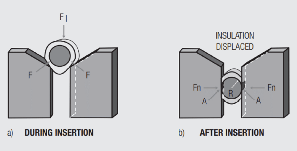
Consider now Figure 2.58b as the conductor moves downward into the electrical contact portion of the slot. The slot design shown consists of two cantilever beams. The conductor will displace both beams creating a force between the conductor and the beams. This force will lead to deformation of the conductor and a change in conductor cross-section as it is inserted into the slot. This deformation creates two contact areas, one against each beam. The contact areas, A, in Figure 2.58 are determined by the deformation of the conductor and the stock thickness of the material from which the contact is stamped. A guideline for an appropriate contact area is that it approximates the cross-sectional area of the conductor being terminated. The wiping action during the insertion of the conductor into the electrical slot enhances the metal-to-metal area in addition to the effects of increasing contact force. The magnitude of IDC contact forces will be discussed in the next section.
IDC Terminal Designs
Figure 2.59 illustrates three variations of an IDC slot design. Recall that for a cantilever beam the contact force due to beam deflection is given by:


where F is the contact force, E is the elastic modulus of the base metal of the contact, D is the deflection of the contact beam, in the case of IDC, by the conductor and, w, l and t are the width, length and thickness of the beam.
In the case of the IDC design in Figure 2.59a, l is the length of the contact from the base of the slot to the point on the beam in contact with the conductor, w is the thickness of the contact beam and t is the dimension of the contact geometry at the base of the IDC slot.
Note that for IDC beam deflections there is an interaction between the beam deflection and the position of the conductor in the slot, which is l, the effective length of the beam. The beam deflection will be given by the reduced diameter of the conductor due to the deformation that occurs as the conductor slides down into the slot.
The parameter t, the effective thickness of the cantilever beam is also more complicated. Rather than deflecting at the attachment point of a cantilever beam, the IDC beam deflection varies with the curvature of the base of the IDC slot. Figure 2.59 shows some variations in the geometry of the base of an IDC slot. Figure 2.59a shows a straight slot. The beam deflection, and the stresses in the beam, will be distributed primarily around the base of the slot. Figure 2.59b shows a straight slot with a circular opening added at the base of the slot. This configuration is sometimes called a “keyhole” slot. The effective thickness of the beam is decreased by the addition of the circular opening and the deflection and associated stresses are distributed over a longer length of the beam yielding a more compliant structure. Figure 2.59c introduces a varying thickness along the length of the IDC beam to further spread out the deflection and stresses. This geometry stores the most elastic energy of the three designs and makes the most effective use of the beam material.


While the mathematics will be different, each of these designs will have a relationship between the beam deflection and the contact force exerted by the deflected beam on the deformed conductor positioned in the slot. Figure 2.60 shows an example of such a relationship for a straight slot IDC. The curve for beam deflection is shown as linear which would be the case if the deformation of the beams was elastic. The band around the beam deflection curve represents the tolerance in control of the slot width. The curve for conductor deformation shows considerable curvature to represent the plastic deformation of the conductor as it is pushed down into the slot and deforms as it deflects the IDC beams. Once again, the band around the conductor deformation curve represents the tolerance in conductor diameter during manufacturing. The “window” where the two tolerance bands overlap shows the expected range in contact force and conductor deformation. The values for contact force and deformation depend on the conductor size and IDC slot/beam geometries. The conductor deformation is typically somewhat larger than for crimping, nominally 25 percent reduction in area. Contact forces are typically much higher than in separable connections, 500 to a few thousand grams compared to 50 to a few hundred for separable interfaces. These forces are sufficient to provide the desired mechanical stability.


While many IDC slots are flat stampings there are also stamped-and-formed dual slot options. Figure 2.61 shows examples of two dual slot contacts. In these designs both of the slots may have an electrical function, or the outside slot, the slot away from the separable contact interface, may be a strain relief slot. The dual electrical slot option will provide enhanced electrical performance due to parallel and redundant contact interfaces. The strain relief option enhances mechanical stability.


The two designs shown in Figure 2.61 are quite different in deformation mechanics. The slots in Figure 2.61a will show similar performance to the stamped slots previously discussed with the exception of contributions due to the coupling link between the slots. The slotted box of Figure 2.61b has a smaller degree of coupling between the two IDC beams than the design of Figure 2.61a. The deflection of the beams takes place along the base of the side walls of the box and will include additional effects due to flexure of the side walls.
Solid and Stranded Conductors
The figures used in this discussion have all shown solid conductors for ease of visualization. In practice, however, stranded conductors, primarily in ribbon cables, outnumber solid in IDC applications and generally meet the same specifications. The difference between solid and stranded conductors in IDC applications is obvious. The deformation of solid conductors is more predictable and controllable than that of stranded conductors because the stranded conductors can move relative to each other as they are inserted into the slot. Such movements change the effective diameter of the stranded conductor bundle, therefore, the deflection of the beams and, in turn, the contact force. Figure 2.62 schematically illustrates the deformation of solid and stranded (seven strand) conductors, of the same wire size, terminated in the same IDC slot design. The tendency towards such conductor reorientation is reduced by the concentric wire construction and the lay of the outer layer of conductors as they wrap around the central conductor. In addition, the residual wire insulation and insertion tooling design, to grip the wire circumferentially or at two points during wire insertion also reduces the potential for conductor reorientation during insertion.


The beam deflection caused by the solid conductor is entirely due to the deformation of the conductor creating two contact areas with the IDC terminal. In contrast the stranded conductor has changed its shape from the original close packed structure, with the six outer conductors abutting the center conductor, to a more open ovalized configuration. Note that four of the seven strands have been deformed against the IDC beams with little strand-to-strand deformation. The contact area produced in a stranded IDC connection appears to be less than that for a solid conductor. It should also be noted that stranded conductors are more prone to cut or broken strands during insertion. The most significant impact of such defects will be a possible reduction in contact force.
Despite these concerns, stranded conductor IDC connectors are able to meet contact area and contact force requirements as evidenced by the inclusion of both solid and stranded conductors as options in many IDC connector product specifications and qualification programs.
Plated and Unplated Conductors
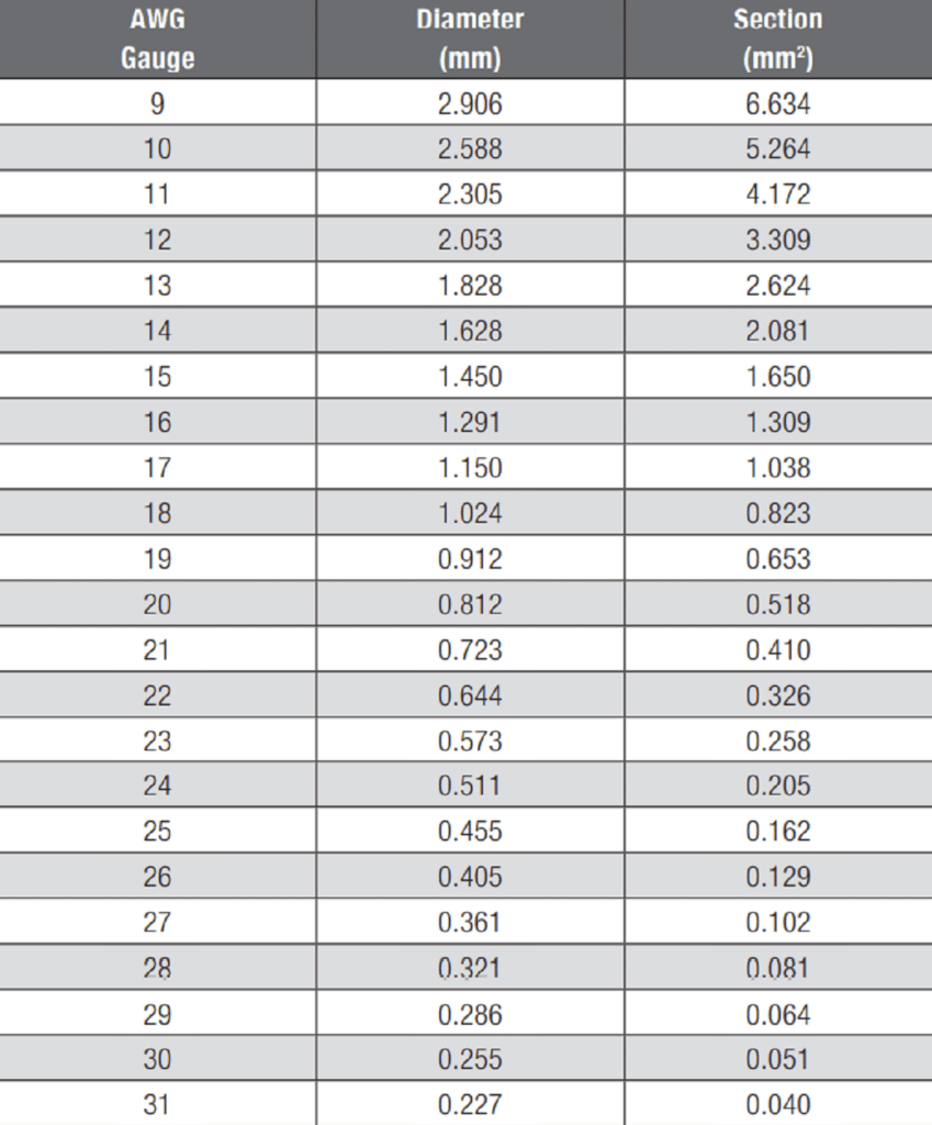
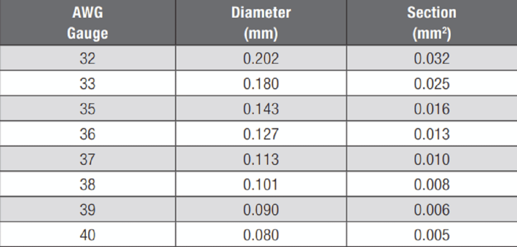
Conductors for IDC applications are generally annealed copper with an elongation of greater than 10 percent to ensure ductile deformation of the conductors on insertion. As noted wire sizes are application dependent, but solid conductors of 0.25 to 3.6 mm nominal diameter and seven strand concentric constructions of 0.05 to 10 mm2 crosssectional area are preferred, although higher strand counts have been used.


Solid conductors can be used without plating, but plated stranded wires are preferred. Platings include tin and silver, for general and high frequency applications respectively.
Strain Relief
Despite the high contact forces of IDC connections, external forces applied parallel to the IDC slot axis can disturb the conductor. Protection against such forces can be important. One of the most popular type is the external strain relief used for 2.54 mm box header (WR-BHD) to avoid breaking IDC connection while operator is pulling directly the flat cable for easier handling (instead of pulling connector).

Summary
To summarize, how does the IDC process address the fundamental permanent connection requirement to create and maintain the integrity of metal-to-meta interfaces? Two, or more, contact areas are created as the conductors wipe against the sides of the IDC slot under the force created by the deflection of the slot beams. The contact area is given by the combination of the deformation of the conductors and the thickness of the IDC slot. The contact force that maintains the integrity of the contact interfaces is the force due to the deflection of the IDC slot beams by the conductor as it deforms and slides down the slot. A guide for the contact area is that it should approximate the cross sectional area of the conductor. The contact forces in an IDC are an order of magnitude higher than those of separable connections to provide the needed mechanical stability. Strain relief features are necessary to resist forces applied parallel to the IDC slot. Both solid and stranded conductors are suitable with plating being recommended for stranded conductor applications.