The contact springs, B in Figure 1.3, are typically manufactured from copper alloys in order to provide three major functional capabilities:
Electrical conductivity
The contact springs provide the electrical connection between the two sub-systems being connected. Copper alloys provide the highest electrical conductivity of commonly used metals when we consider the material price as well.
Separable Connections and Contact Force
As mentioned previously, the separable contact interface in a connector is created and maintained by the contact normal force generated by deflection of the receptacle contact springs by the plug contact on mating. For this reason, the contact normal force is arguably the most important connector design parameter as will be discussed in seperable connection chapter.
Plug contacts, Figure 1.8, include pads on a printed circuit board and rectangular or round pins, respectively. Receptacle contacts come in a variety of spring geometries to serve different application needs and requirements.
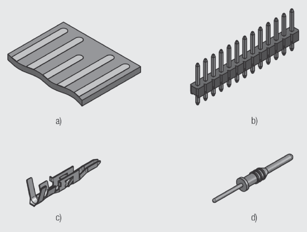
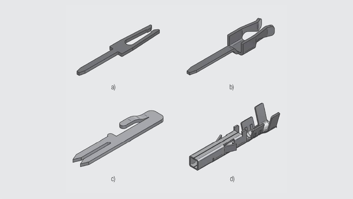
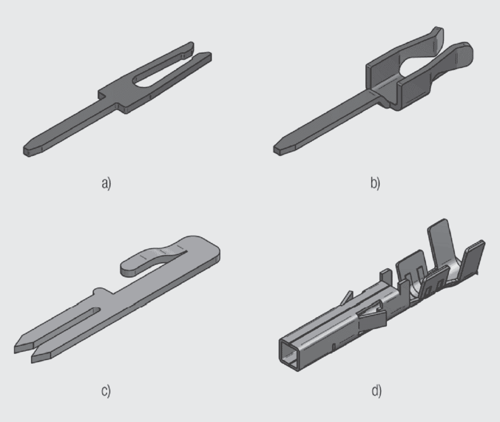
Figure 1.9 shows several receptacle spring geometries intended to provide functional capabilities, such as accommodating tolerances, and controlling the range of contact force in the connector. Copper alloys provide a good balance of spring characteristics and manufacturability. All of these contacts mate to a pin or post but require different amounts of forming to provide performance enhancements. Figure 1.9a is a simple flat stamping having twin cantilever beam contacts. The limitation of this contact is that the mating surfaces are the sheared edges of the stamping. This means a rough and uneven mating surface which is undesirable. If the contact was to be tin plated it could be used as is. But if silver or gold plating is desired the sheared edge would have to be improved eliminating the cost advantage. Figures 1.9b and 1.9c are simple means for eliminating the sheared edge issue. In Figure 1.9b the contact beams are simply twisted by 90 degrees so the mating surface becomes the rolled surface of the strip. The spring system is no longer a simple cantilever beam due to the twist which stiffens the beam. In Figure 1.9c the contact beams are folded upward to make the contact surface a rolled surface. The spring system is no longer a cantilever beam. The beam deflection will also open the U shape at the base of the beams. Finally, Figure 1.9d includes multiple forming operations to provide a crimped permanent connection with an insulation grip, latching beams to retain the contact in the housing and a box entry which provides an alignment feature as the pin or post is inserted into the contact.
Permanent connections
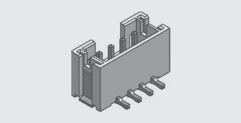
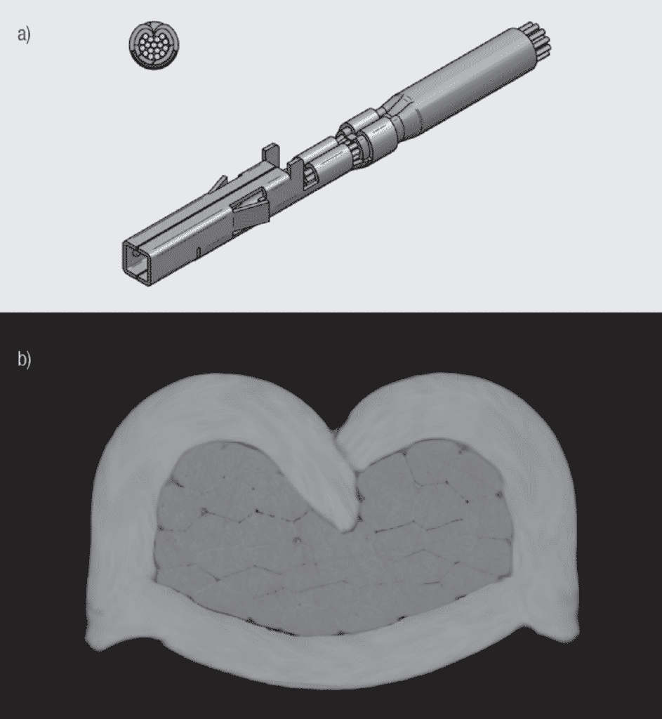
A connector also includes permanent connections between the connector contacts and the sub-systems being connected. Permanent connection methods used in connectors include both metallurgical and mechanical technologies. The primary metallurgical permanent connection method is soldering. There are two basic soldering technologies used in connectors, through hole and surface mount, examples of which are shown in Figures 1.10 and 1.11 respectively. The long solder tails in Figure 1.10 are inserted into plated through holes in a Printed Circuit Board (PCB) and wave soldered. The solder tails in Figure 1.11 are reflow soldered to surface pads on a pcb. Wave and reflow soldering will be reviewed in Chapter II/Design/Selection/Assembly. The two major mechanical permanent connection technologies are crimping and insulation displacement, examples of which are shown in Figures 1.12 and 1.13 respectively. Crimp and IDC technologies will be reviewed in Chapter II/Design/Selection/Assembly. Copper alloys are advantageous for both metallurgical and mechanical permanent connections because they are solderable/weldable and readily stamped and formed into the configurations needed to create mechanical permanent connections. Details of these technologies will be provided in Chapter II/2.2.2 Permanent Connections area. Details on copper alloy selection and manufacturing technologies as applied to connectors will be discussed in Chapter I/1.4 Connector Materials and Processes.