A schematic illustration of a four-position terminal block is shown in Figure 2.78.


THR compatibility requires a housing material that is capable of withstanding the highest temperatures of reflow soldering (+245 °C for this product according to IPC/JEDEC J-STD-020D). There are two concerns relative to this temperature exposure. The first relates to the effect of soldering temperatures on the moisture content of the polymer. The absorbed moisture expands under the soldering temperature exposure thus producing blisters or bubbles in the housing, as illustrated in Figure 2.79.


The second effect is the melting/distortion of the housing due to the temperature exposure as illustrated in Figure 2.80.


To avoid these potential problems, Würth Elektronik has changed the material of THR terminal blocks to a Liquid Crystal Polymer (LCP). LCP polymers can meet SMT processing temperature requirements; in addition, they have lower thermal expansion coefficients, which is an important consideration when thermal expansion mismatch stresses come into play.
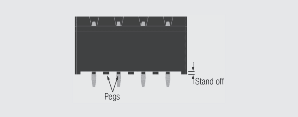
THR compatibility also requires changes in the housing design. In particular, standoffs in the housing are required to allow room for the solder paste and to promote air flow under the housing to facilitate the reflow soldering process. These features are illustrated in Figures 2.81 to 2.83. Figure 2.81 shows a side view of a THR compatible terminal block housing with stand-off pegs.

Figures 2.82a and 2.82b respectively show the planar base of a standard terminal block and the base of a THR compatible terminal block with stand-off features.
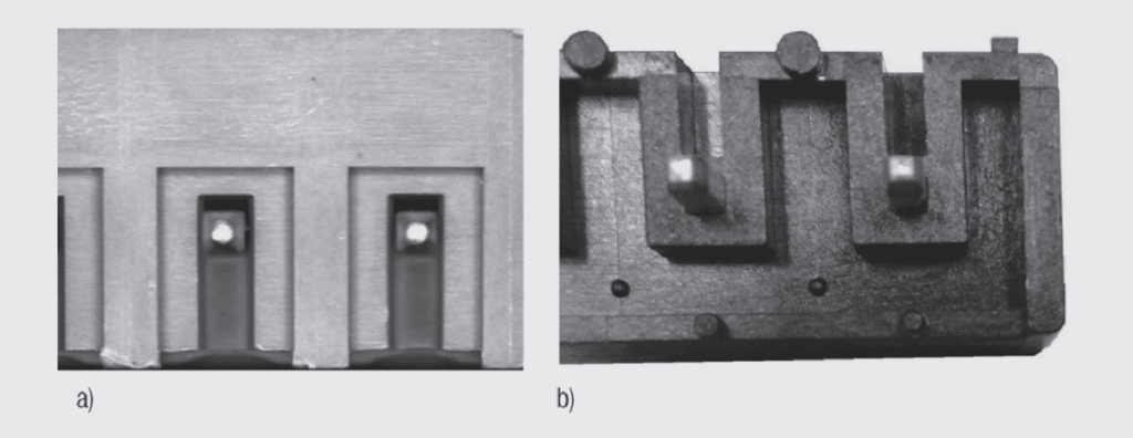
b) THR terminal block base showing stand-off features
The stand-off clearance between the connector base and the PCB should be at least 0.3 mm to prevent the base of the connector from touching the solder paste deposit. In addition, contact between the stand-off features and the solder deposit should be avoided to minimize the potential for solder balling during reflow.
Figure 2.83 shows the air flow paths through the THR compatible terminal block housing that are created by the stand-off features.


For manufacturing efficiency it is also desirable that the housing design should be compatible with vacuum pick and place processes. The pick and place process may limit the size of the connector that is suitable for THR connectors.