
This article written by Steven Keeping, contributed By Digi-Key, discusses the key requirements for board-to-board connectors to meet high-speed automotive assembly needs.
Designers of automotive systems need to carefully select and apply connectors so they perform reliably both physically and electrically in environments where they are subjected to temperature and humidity extremes, contamination, and vibration. Meeting and sustaining automotive performance and reliability requirements is becoming increasingly challenging as vehicles become powerful “computers on wheels”. The connectors must be able to handle more transmission lines in tighter spaces with communication speeds of several gigabits per second that are necessary to accommodate standards such as 10GBASE-T1 and PCI Express version 3 (PCIe 3.0).
To make things even more challenging, automotive companies demand very high production volumes, so electronics assembly companies need to turn to high-speed assembly machines to keep up. However, it’s difficult to keep production rates and yields high while at the same time accurately placing the connectors such that they later mate without problems.
These challenges can be met using physically and electrically robust floating contact connectors that absorb positional shifts or misalignments encountered during automated assembly.
This article describes the electrical signal and physical application and manufacturing demands facing automotive connectors. It then introduces floating connectors from JAE Electronics that designers can use to meet these demands. Specifics on high-speed communications standards and suitable connector selection and application are included, along with guidance on how to select connectors for high-speed automotive communications protocols such as 10GBASE-T1 and PCI Express version 3 (PCIe 3.0).
High-speed communications protocols in brief
10GBASE-T1 is one of a family of 10 gigabit Ethernet (10 GbE) standards that offers transmission of Ethernet frames at a rate of 10 gigabits per second (Gbps). 10GBASE-T1 is an “Automotive Ethernet” solution that operates using twisted-pair cables over distances of up to 15 meters (m). The 10 Gbps data throughput is the fastest automotive communication standard, and it can support applications such as autonomous driving.
PCIe 3.0 is another high-speed serial computer expansion bus standard. It provides for up to 8 gigatransfers per second (GTps). In a high-end “x16 lane” implementation, 8 GTps equates to an aggregate data transfer rate of 126 Gbps.
Traditionally used as a high-speed bus in PCs, the technology is now being targeted at automotive applications for the vehicle of the future because the hardware design guarantees that transmitted data packets arrive at the intended destination. This makes for a highly reliable system that is suitable for autonomous driving.
Connectors for high-speed automotive communications
High-speed communication protocols require high-quality connectors. Not only must they provide a robust and reliable connection to ensure excellent signal integrity, but they also must be relatively easy to disconnect and reconnect over many years of service. They must also be able to accommodate many pins and receptacles on a small pitch to ensure compact size with multi-lane connectivity.
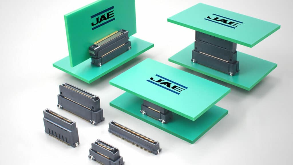
An example of a modern connector family for high-speed communication protocols such as 10GBASE-T1 and PCIe 3.0 is the MA01 series from JAE Electronics. These connectors offer features such as rolled surface contacts and two-point contact structures to ensure secure mechanical and electrical connections even under the vibration, shock, and temperature extremes typical of automotive applications (Figure 1).


Offered in various stacking heights between 8 and 30 millimeters (mm) (Figure 2) and capable of transmitting the 8 Gbps speeds demanded by 10 GBASE-T1 and PCIe 3.0, the MA01 series connectors are ideal for applications such as automotive board-to-board digital control units. The connectors feature low insertion and removal forces and include keying to prevent incorrect mating. The connectors feature a wide operating temperature range of -40 to 125°C.


One example from the range is the MA01F030VABBR300. This connector is an automotive grade, high-speed transmission, board-to-board connector. It features 30 positions on a pitch of 0.635 mm within a body measuring 20.925 x 8.8 x 12.3 mm. The contacts are made of copper alloy with a 0.1 micrometer (µm) (min) layer of gold plating. The connector’s electrical specification is 0.5 amps (A) rated current and 50 volts AC rated voltage. It is designed for up to 100 mating cycles.
The MA01F030VABBR300 is designed to mate with the MA01R030VABBR600 to form board-to-board connections for high-speed automotive applications (Figure 3).
Overcoming assembly challenges
High-volume electronics manufacturing demands the use of robot assembly technology. However, the automatic placement machines used for the job do have mechanical limitations. This can result in tolerances in component positioning. While slight positional errors are typical and are not a problem for active and passive components, they can cause issues when mating multi-position, fine-pitch connectors. The problem is compounded because a typical connector doesn’t present a flat surface for the placement machine vacuum nozzle to gain proper purchase.
With typical pin-to-pin pitches of less than a millimeter, it doesn’t take much misalignment when mating connectors to result in damaged contacts.


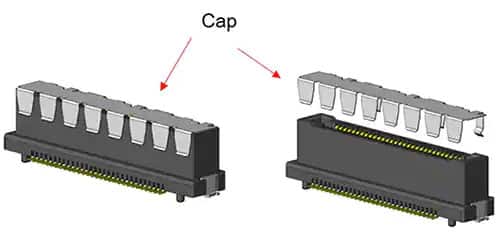

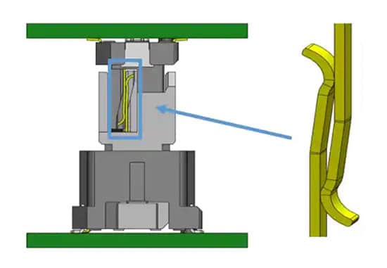
To overcome this, the JAE MA01F030VABBR300 features floating contact technology that allows a movement of ±0.5 millimeters in both X and Y directions. This float corrects for positional shifts or misalignment caused during mounting by automated machinery. The connectors come with a removable cap that provides secure purchase for placement machine vacuum nozzles. The cap also serves to prevent large debris from entering the mating area prior to connector mounting (Figures 4 and 5).
The female side of the board-to-board connector, the MA01R030VABBR600, is a rigid connector because only one side of the connection needs to float to accommodate placement positional tolerances.
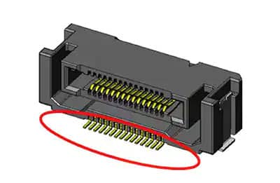
Another feature of the MA01 series connectors that eases the assembly process is a clear view of the solder joints where the connector meets the pc board. Conventional connectors typically conceal these solder joints, making inspection difficult and risking in-service failures (Figure 6).
Ensuring trouble-free mating
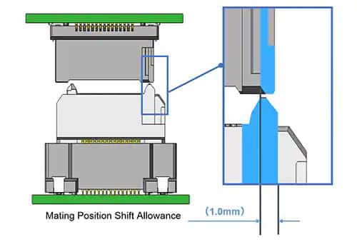
The MA01 series’ floating connector technology is useful when compensating for placement positional errors, but greater misalignment can occur when the connectors are manually clipped together. Such misalignment can often happen when the top and bottom pc boards holding the two halves of the connector are brought together “blind,” making it all too easy to misalign the delicate contacts. Worse yet, the connector might feel like it has properly mated even if the contacts have been damaged during the process. Such misalignment can occur in both the X and Y horizontal directions.
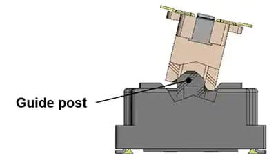
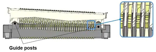
The JAE connectors include guideposts that prevent improper connection, even if the connectors are significantly misaligned in either or both X and Y directions during the mating process. The guidepost is molded into the connector body and steers the two halves of the connector into the correct engagement position (Figures 7, 8, and 9).


Once mated, the connector’s floating contact feature allows it to absorb the shock and vibration typical of automotive applications without risk of contact damage.
High-speed connector selection
Designing high-speed communications systems is tricky. Even before the designer starts to consider the signal integrity of a given connector, the associated pc board’s layout must take into consideration factors such as target impedances and routing of the high-speed differential signal channels to limit crosstalk and losses. However, assuming the designer has taken these and other key design factors into account, then the connector can play a major role in the ultimate bandwidth, raw data throughput, and signal integrity of the system.
The first thing to check when selecting a high-speed connector is the maximum bandwidth for the desired communication protocol. There’s little point in designing a system that can work at high speed if the connector is not capable of handling the protocol’s operational frequency. A simple way of doing this is to pick connectors that are certified compliant with the relevant protocol’s standard. That way, the designer can be confident that the connector has been specifically designed to ensure maximum throughput and bandwidth.
A compliant connector will also feature the target impedance for the relevant high-speed protocol (typically 50 ohms (Ω)). Other selection factors such as the material from which the connector is made, board mounting style, and dimensions are important, but have less impact on signal integrity.
While compliance certification will give the designer confidence that the connector can do the job, it is important to test the shortlisted connector on a test pc board of similar or identical layout to the production item. The datasheet or testing the connector in isolation might not exhibit signal integrity issues that can occur in real-world use. Testing on a prototype assembly will give a clear indication of signal reflection and/or distortion issues.
The key measurements for determining the signal integrity of the connector are the S-parameters and the eye diagram. The S-parameters indicate signal return and insertion losses in the frequency domain. They should be measured for the working circuit with the connector in place, and then compared to the results with the connector removed to evaluate its impact on signal integrity.
An oscilloscope-generated eye diagram is a visualization of the circuit’s performance in the digital domain. It is the standard method for visualizing losses, crosstalk, intersymbol interference (ISI), and bit error rates. Again, the tests should be performed with and without the connector to establish its impact on signal integrity.
Conclusion
It’s challenging for designers to meet the demanding physical and electrical performance requirements of automotive board-to-board connectors, while also avoiding connector damage due to poor positioning and misalignment tolerance during high-speed automated assembly. Designers can overcome the challenges using JAE Electronics’ MA01 series connectors.
As shown, the MA01 connectors are compliant with multi-gigabit communication protocols and offer a robust and reliable solution with low-resistance insertion and disconnect. Moreover, the connectors have also been designed with fast assembly in mind. Features such as removal caps, floating connectors, and guideposts allow for greater tolerances in board mounting and blind board-to-board connection without the risk of misalignment and damage to contacts.