
There are two processes used to convert polymer resin pellets to a connector housing, compression/transfer molding and injection molding. Before discussing those processes, however, another method of polymerizing the starting resin must be mentioned for completeness, condensation polymerization.
Recall that addition polymerization occurs by the addition of individual mers to existing polymer chains under the influence of temperature, pressure and catalysis. Some typi cal addition polymers include polyethylene, polypropylene, polyvinyl chloride (PVC) and polytetrafluoroethylene (PTFE).
Condensation polymers are so called because the bond breaking process that leads to polymerization occurs through a chemical reaction between different mers, an organic acid and an alcohol, esterification, with the production of by-products, condensates. The most common condensates are water and methyl alcohol, CH4O. Polymers produced by the esterification reaction are called polyesters. Nylons, polyamides, are also produced by condensation polymerization.
Compression/Transfer Molding
Compression and transfer molding processes are used primarily for molding of cross linking, thermosetting, polymers. The processes are similar, differing in how the polymer resin is presented to the mold. In compression molding a fixed amount of material is placed into the mold which is then pressurized and heated to the molding temperature. In transfer molding the material is transferred from a transfer pot into the mold at controlled temperature and pressure. Molding temperatures are high and time in the mold is long in order to optimize the cross linking of the polymers with a significant cost impact. Any molding scrap, from sprues and runners in the mold to underfilled parts is scrap.
Injection Molding
Injection molding is similar to transfer molding in that the resin pellets are held in a hopper and transferred, after heating/mixing/plasticating, by injection under pressure into a mold. While some thermosets are injection molded, the vast majority of connector housings are thermoplastic polymers.
There are two major components of an injection molding system, the injection system and the clamping system, shown in Figure 1.39. The injection system includes:
Hopper: The hopper holds the polymer resin pellets prior to transfer into the plasticating section. The hopper can be refilled as needed because the pellets are not held under controlled temperature.


Plastication: Plastication includes two steps, heating of the resin and mixing of the heated pellets into a homogenous polymer melt at a controlled temperature. Heat is supplied by heater bands around the injection barrel. A reciprocating screw within the injection barrel mixes the heated polymer until it is ready for injection into the mold. The reciprocating screw then moves forward injecting the polymer under controlled pressure through a nozzle into the gating system of the mold. The pressure is maintained during the cooling cycle of the process. The nozzle then retracts and the hopper fills the plastication section with polymer for the next molding shot.
The molding system includes
Clamping System: The clamping system contains and supports the mold. It consists of a fixed front plate which engages the nozzle during injection of the polymer and a movable back platen which holds the mold closed under a clamping pressure dependent on the size of the mold and polymer being molded and moves backward on completion of the cooling time to open the mold and eject the molded parts.
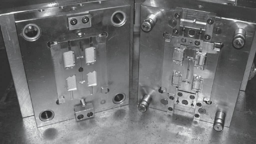
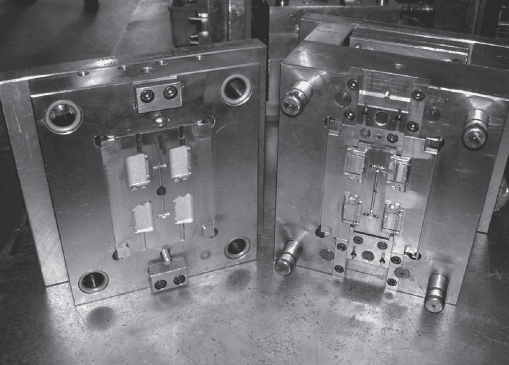
Mold: The mold may be a single or multi-cavity mold depending on the economics of the part being molded. A multi-cavity mold will contain sprues and runners to interconnect the individual cavities. Mold design of multi-cavity molds can be complex in order to balance the polymer flow to the individual cavities. For thermoplastic polymers, the sprue and runner parts may be salvaged and reused depending on the requirements on the part. An example of a multi-cavity mold is provided in Figure 1.41.

As noted with the processing of metals from casting to strip, the principles of injection molding are straight forward, but many design challenges must be met to ensure consistent high volume manufactured parts.