As noted previously, the definition of connector type is determined by several factors including the contact spring geometry, the housing geometry and the method of permanent connection. In this discussion the LOI levels where the connector systems are used will also be identified for reference. The discussion of connector types will be general. Many variations on each type exist with specifics depending on the industry being served. This is especially the case in computer/telecom applications.
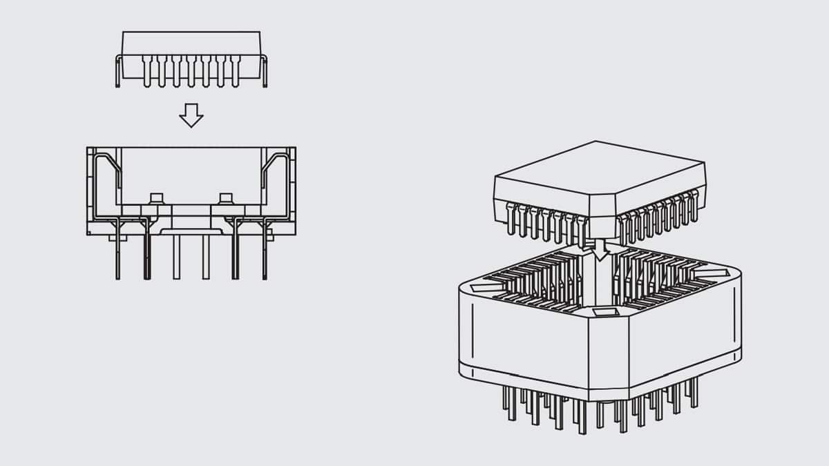
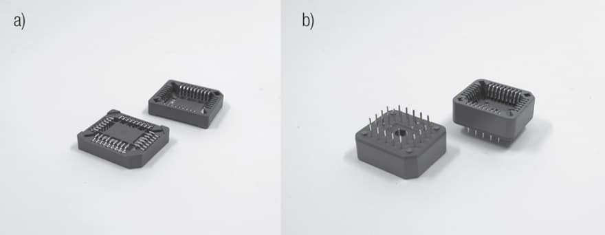
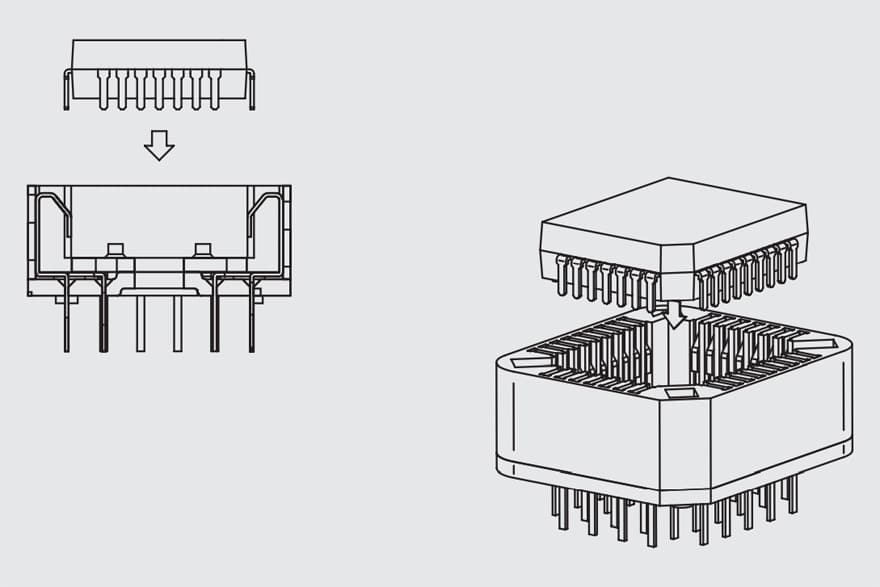
Sockets and chip carriers, which are also sockets, are used primarily at Level 1. There are two styles of chip carriers depending on the functionality and pin count of the IC. Low pin count ICs (less than 100) have their leads around the periphery of the IC. Chip carriers for these applications may be through hole or SMT soldered to the board, Figure 2.123a and b respectively. The chip carrier contacts are typically tin plated cantilever beam designs, Figure 2.124.
As CPU technology and functionality increased chip carriers have evolved to meet demands to interconnect with high lead count (over 1000 positions) integrated circuits of three types, Pin Grid Array (PGA), Land Grid Array (LGA) and Ball Grid Array (BGA) packages. As the names indicate, the IC leads are distributed in arrays over the base of the IC package. PGAs have pins extending from the IC package, LGAs have lands on the package base and BGAs have solder balls on the package base. Needless to say the sockets for these IC package types are different. All of these packages can be connected to a PWB by soldering or mechanically. PGAs are wave soldered and LGAs and BGAs are typically reflow soldered. The mechanical connections in each case are pressure connections, analogous to separable connections discussed in Chapter II/2.2 Contact Springs, though the PWB connection is intended to be permanent. The contact designs differ among the three types. The contact finish is often gold over nickel. Due to the high pin counts mechanical connections are mechanically assisted by a variety of means. The IC package is also connected to a heat sink.


