Samtec articles explore benefits and reasons why to use a flyover cable system.
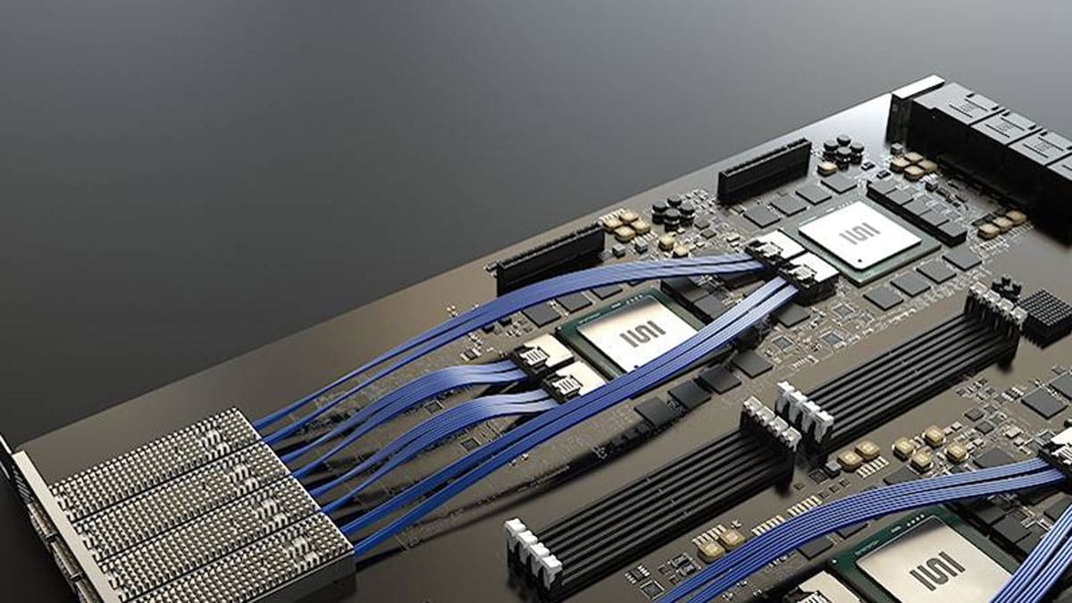
Samtec’s Flyover® cable systems are designed to get signals off the PCB in order to improve signal integrity, increase design flexibility, and optimize thermal performance. These products route high-speed signals through low-loss, low-skew twinax cable.
They operate across distances that can be up to several feet long while removing the need for clock data recovery circuits (CDRs) or retimers. In a recently published white paper, Samtec Senior Field Applications Engineer, Anthony Fellbaum, provides measured data and examples to explain why a cable solution can be better in a high-speed design than a PCB trace. It also addresses concerns such as cable management and cost.
Analyzing Performance
In the published analysis, Samtec’s Flyover cable demonstrates significantly lower loss than any PCB grade material. Figure 1 compares the magnitude (in dB) of insertion loss for three typical PCB materials and two gauges of Samtec Flyover cable (30 and 34 AWG). A 10” length comparison is displayed for easier scaling.
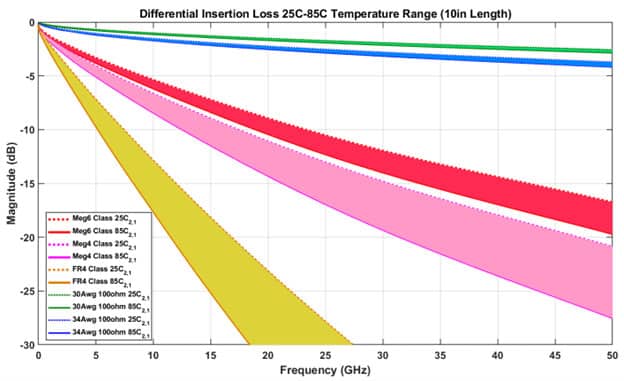
In Figure 1, for a typical high-speed signal running at 14 GHz Nyquist, the traditional PCB material (shown in yellow) is very lossy. So, the designer would likely select a higher-grade material (shown as light and dark pink in the graph), where the loss characteristics are significantly better. (Note that temperature variations can also degrade loss performance significantly.) However, even the best PCB performance is well below the Samtec low-skew high-speed twinax (green 30 gauge, blue 34 gauge in Figure 1) cable.
Specifically, within the Samtec Flyover system, a 30 AWG cable demonstrates insertion loss (IL) of 1.21 dB for 56 Gbps PAM4/14 GHz Nyquist or -1.8 dB for 112 Gbps PAM4/28 GHz Nyquist. The Samtec 34 AWG cable demonstrates insertion loss of -1.9 dB for 56 Gbps PAM4/14 GHz Nyquist or -2.9 dB for 112 Gbps PAM4/28 GHz Nyquist.
It is worth noting the stability of these materials over temperature and relative humidity (0-60% relative humidity included in the temperature plot). As seen in the chart above, PCB materials have a significant drop in loss performance over temperature. Samtec’s Eye Speed® Twinax cable, on the other hand, has very stable performance, thanks to the low moisture absorption properties of the dielectric used in the cable.
The plots above only compare PCB trace vs. cable conductors. In order to implement a cable system, a connector is required. To provide a full picture of the loss of a cabled solution, Figure 2 displays insertion loss with added connectors. The plot describes the measured insertion loss performance of Samtec’s NovaRay® Flyover system with a length of 0.25 m. You can see added loss for the interconnect, which includes the footprint and breakout region design. Test cables and traces are de-embedded up to ~2 mm of the connector footprint.

Summary
The key takeaway is: Samtec remains committed to advancing the state-of-the art in cable design. As a result, Samtec cables offer a unique construction with industry-leading loss performance.
The Flyover product line includes Flyover panel assemblies, Flyover mid-board assemblies, Si-FlyTM ASIC adjacent technology, FireFlyTM Micro Flyover SystemTM (copper or optical), and backplane cable assemblies.


