• Latest
  • Trending

How the Connector Blade Assignments Impact Power Integrity 

August 15, 2023

binder Unveils Quick Lock Ruggedized Power Bayonet

October 3, 2023

Connector Temperature Rise and Derating

September 29, 2023

Connector Raw Material Costs Decreased 6.9 Percent in Q2 2023

September 27, 2023

Webinar PCBs: RIGID.flex with Flexible Soldermask or Coverlay?

September 20, 2023

Samtec Expands with a New Cable and RF Connector Manufacturing Facility in Pennsylvania

September 20, 2023

KYOCERA AVX Unveils New Series Poke-Home Single Contacts

September 20, 2023

Murata Announced Completion of New Plating Research Building in Japan

September 19, 2023

RF Compression-Mount Connectors Enhance Millimeter Wave Designs

September 1, 2023

Würth Elektronik Introduces micro SIM Card Interface with Card Detection

August 31, 2023

Yamaichi Extended Board-to-Cable Connectors for Battery Management

August 15, 2023

How to Maintain 50 Ohms RF Transmission Path

August 15, 2023

Understanding the Benefits of a Flyover Cable System

July 28, 2023
  • Privacy Policy
inter-connection blog
  • Home
  • Knowledge base
  • Sister Sites
    • Passive Components Blog
    • PCNS Symposium
    • The Passives Times
    • EPCI Home
  • About
No Result
View All Result
  • Home
  • Knowledge base
  • Sister Sites
    • Passive Components Blog
    • PCNS Symposium
    • The Passives Times
    • EPCI Home
  • About
No Result
View All Result
inter-connection blog
No Result
View All Result

How the Connector Blade Assignments Impact Power Integrity 

August 15, 2023
A A

Samtec releases white paper that summarizes some of the important considerations of connector pin and blade assignment in combination power and signal connectors that may impact power integrity.

If you get your power design right, it protects the signal integrity margin and improves power and thermal efficiency. Some connectors combine power blades in addition to digital signal pins, which adds complexity. For these types of connectors, it is important to understand how the blade assignments impact power delivery as well as how the pin and blade assignment could affect signal-to-power and power-to-signal crosstalk.

RelatedPosts

Samtec Expands with a New Cable and RF Connector Manufacturing Facility in Pennsylvania

RF Compression-Mount Connectors Enhance Millimeter Wave Designs

How to Maintain 50 Ohms RF Transmission Path

While the preferred pin assignment in high-speed connectors, including the Samtec AcceleRate® connector family, is well documented and understood, less support material is available on power connectors and power-signal connector crosstalk.

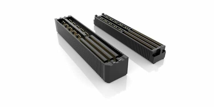
The UDX6 family of connectors, in particular, enables higher density designs by providing an AcceleRate high-speed connector and an upgraded mPOWER® blade connector within the same housing (featured image). These connectors achieve 56 Gbps PAM4 speeds and feature rotated power blades for 22 Amps/blade and simplified breakout region (BOR). The white paper steps through detailed analysis of the impact of pin and blade assignments, and it ends with showing a preferred pin and blade assignment based on the results.

The inductance of the power delivery path, which influences the transient response of the power network, changes significantly with the blade assignment. If the inductance of the power delivery path matters for the application, it is typically best practice to minimize the loop inductance formed by the power and power-return paths. (The loop inductance formed by the blades is directly proportional to the size and shape of the loop.)

Conclusion
In conclusion of the white paper: a high-speed block of pins, assigning signal and ground pins adjacent to each other is the accepted norm. In the power-blade block, assigning power and ground to adjacent blades will provide two benefits. It minimizes the power delivery inductance and simultaneously minimizes the crosstalk between power blades and signal pins. A preferred pin and blade assignment corresponding to the above considerations is shown in Figure below.
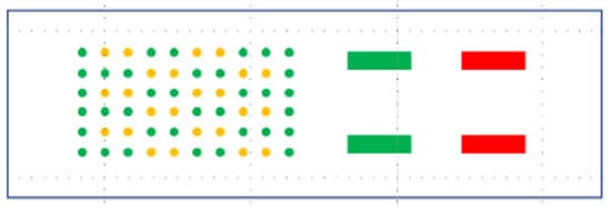
Preferred pin and blade assignment sketch. Green: GND, Red: PWR, Yellow: signal. Source: Samtec

Related

Source: Samtec
Next Post

Yamaichi Extended Board-to-Cable Connectors for Battery Management

Würth Elektronik Introduces micro SIM Card Interface with Card Detection

RF Compression-Mount Connectors Enhance Millimeter Wave Designs

Popular Posts

  • Crimped Connections

    0 shares
    Share 0 Tweet 0
  • THR (Through Hole Reflow) Technology: Introduction & History:

    0 shares
    Share 0 Tweet 0
  • Basic Principles of Connectors

    0 shares
    Share 0 Tweet 0
  • The Electrical Interface: Contact Resistance

    0 shares
    Share 0 Tweet 0
  • Space Saving Molex Connector in AR/VR System designs

    0 shares
    Share 0 Tweet 0

Subscribe to Blog via Email

Enter your email address to subscribe to this blog and receive notifications of new posts by email.

Archive

2023
2022

Newsletter Subscribe

  • About
  • Inter-Connection Blog
  • Inter-Connection News
  • Knowledge base
  • NEWS
  • Privacy Policy
  • Sister Sites
  • Subscribe

© 2023 EPCI - Premium Passive Components & Inter-Connect News

No Result
View All Result
  • About
  • Inter-Connection Blog
  • Inter-Connection News
  • Knowledge base
    • Applications
    • Basic Principles of Connectors
    • Design Selection Assembly
  • NEWS
  • Privacy Policy
  • Sister Sites
  • Subscribe

© 2023 EPCI - Premium Passive Components & Inter-Connect News

This website uses cookies. By continuing to use this website you are giving consent to cookies being used. Visit our Privacy and Cookie Policy.