Samtec releases white paper that summarizes some of the important considerations of connector pin and blade assignment in combination power and signal connectors that may impact power integrity.
If you get your power design right, it protects the signal integrity margin and improves power and thermal efficiency. Some connectors combine power blades in addition to digital signal pins, which adds complexity. For these types of connectors, it is important to understand how the blade assignments impact power delivery as well as how the pin and blade assignment could affect signal-to-power and power-to-signal crosstalk.
While the preferred pin assignment in high-speed connectors, including the Samtec AcceleRate® connector family, is well documented and understood, less support material is available on power connectors and power-signal connector crosstalk.
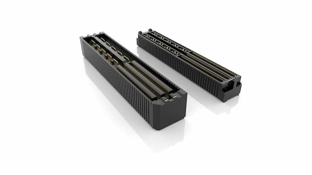
The UDX6 family of connectors, in particular, enables higher density designs by providing an AcceleRate high-speed connector and an upgraded mPOWER® blade connector within the same housing (featured image). These connectors achieve 56 Gbps PAM4 speeds and feature rotated power blades for 22 Amps/blade and simplified breakout region (BOR). The white paper steps through detailed analysis of the impact of pin and blade assignments, and it ends with showing a preferred pin and blade assignment based on the results.
The inductance of the power delivery path, which influences the transient response of the power network, changes significantly with the blade assignment. If the inductance of the power delivery path matters for the application, it is typically best practice to minimize the loop inductance formed by the power and power-return paths. (The loop inductance formed by the blades is directly proportional to the size and shape of the loop.)
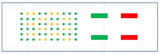
Conclusion
In conclusion of the white paper: a high-speed block of pins, assigning signal and ground pins adjacent to each other is the accepted norm. In the power-blade block, assigning power and ground to adjacent blades will provide two benefits. It minimizes the power delivery inductance and simultaneously minimizes the crosstalk between power blades and signal pins. A preferred pin and blade assignment corresponding to the above considerations is shown in Figure below.