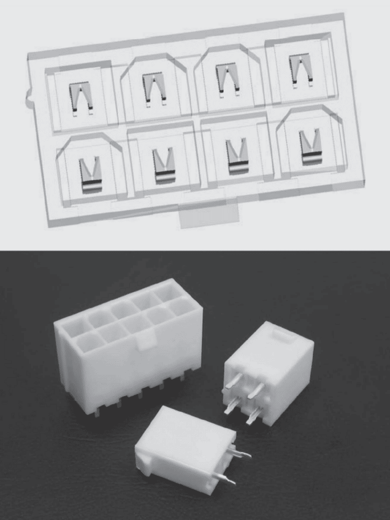
The connector housing, A in Figure 1.3, is the most obvious connector component and has four major functions:
Electrical insulation
All connectors have at least two contacts, input and output, which must be electrically insulated from each other. Most connectors have many more positions providing power or signals to the functional elements of the device. These multiple positions, too, must be electrically insulated from each other. Socket connectors for integrated circuit packages, for example, are available with more than a thousand positions. The insulation characteristics of a connector housing are dependent on both the design and material of the housing as will be discussed in Chapter II.
Dimensional stability
The two halves of the housing must mate together and, therefore, their mating features must be of corresponding shapes and on the same centerlines. The dimensional control required, obviously, depends on the size and the centerline spacing of the housing. Centerline spacings can vary from 0.3 mm (0.100 in) to 10 mm or even higher with corresponding decreases in dimensional tolerance requirements. The ability to realize these levels of dimensional control, both during molding of the housings and in field applications is an important consideration in housing design and material selection.
Mechanical support
In many connector designs the contacts are “latched” into the housing for mechanical support as well as dimensional control. Because spring deflections are responsible for creating the contact force, the mechanical stability of the support provided by the connector housing can have a significant impact on the spring characteristics of such connectors. Once again, this requirement impacts on the design and materials choices for the housing.
Environmental shielding
Most contact springs are made from copper alloys which are susceptible to corrosion reactions with oxygen, sulfur and chlorine, all of which are present in typical connector applications. Details of these processes will be provided in the second part of this chapter, Contact Finishes. At this point, it suffices to say that the design of the connector housing can have a significant impact on the environmental stability of a connector by shielding the contacts and contact interfaces from the environment.
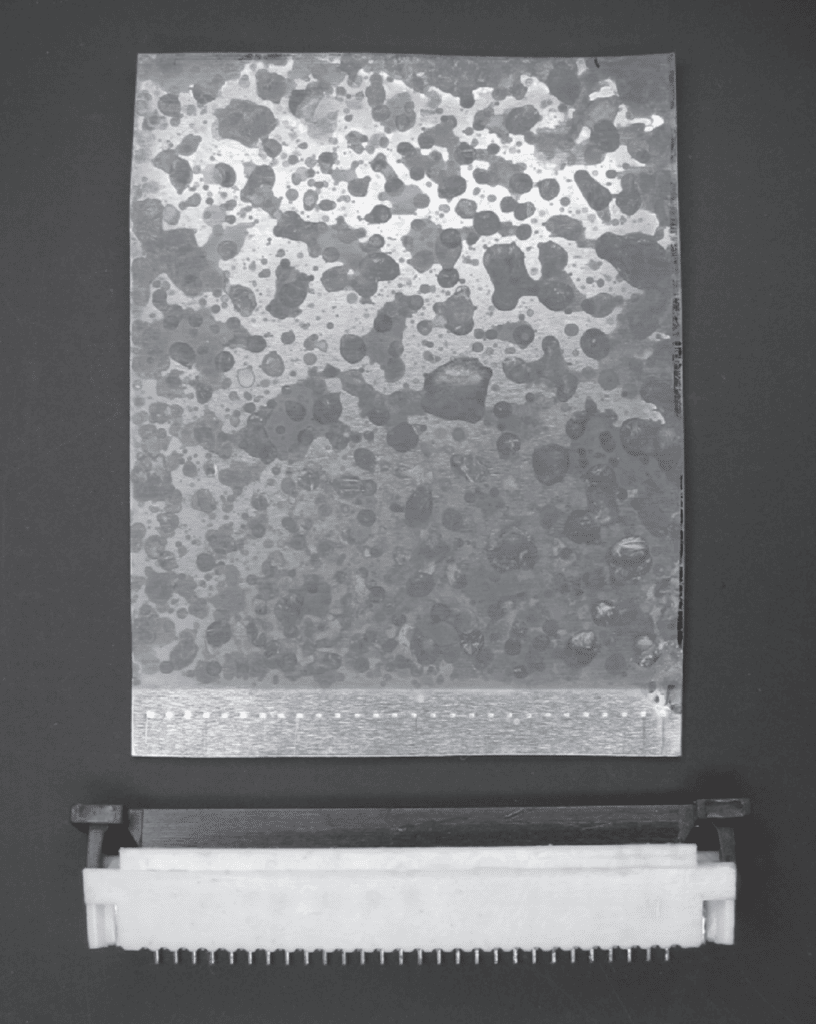
Figure 1.4 illustrates this shielding effect. The coupon shown is a copper plate. The coupon shown was exposed to a sulfur bearing environment while mated with the ZIF connector shown. Note the severe corrosion of the exposed portion of the coupon as compared to the shiny surface of the portion contained within the housing. Note also the wiping marks made by the receptacle contact springs as the coupon is inserted into the connector. This illustrates the cleaning effect that occurs during mating to wipe away surface films and contaminants.
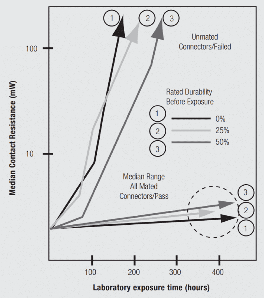
More important, however, is the data shown in Figure 1.5. This data will be discussed in detail in Chapter II/2.1 Contact Finishes. At this point it is sufficient to note that the data showing significant increases in contact resistance was from connectors which were exposed to the test environment unmated. That is, the plug and receptacle halves were exposed separately, while the stable resistance data was taken from mated connectors. The effectiveness of housing environmental shielding is clear. The shielding effect of connector housings provides an important contribution to the ability of connectors to remain functional in harsh environmental applications.
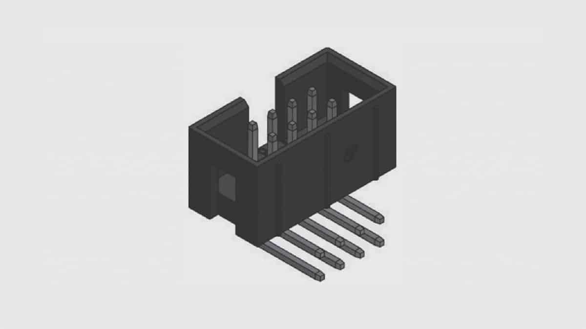
Connector housings vary in pin count from one to over a thousand, and in complexity from simple headers, Figure 1.6, to housings incorporating channels for air flow, Figure 1.7. Connector housing design, material selection and manufacturing practices will be reviewed in Chapter II/Design/Selection/Assembly.