inter-connection blog
  • Home
  • Knowledge base
  • Sister Sites
    • Passive Components Blog
    • PCNS Symposium
    • The Passives Times
    • EPCI Home
  • About
No Result
View All Result
  • Home
  • Knowledge base
  • Sister Sites
    • Passive Components Blog
    • PCNS Symposium
    • The Passives Times
    • EPCI Home
  • About
No Result
View All Result
inter-connection blog
No Result
View All Result

Connector Structure

October 2, 2023
A A

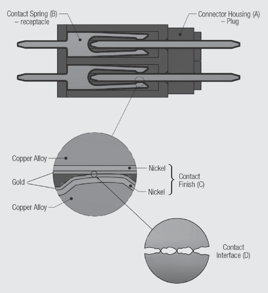
Consider now a structural definition of a connector. There are four basic components in a connector. They are:

A. the connector housing
B. the contact springs
C. the contact finish
D. the contact interface

RelatedPosts

What is RF Connector

Connectors Explained

KYOCERA AVX IDC RF Shark Fin Connectors for Antennas Vehicle Systems

This chapter will provide a basic introduction to connector housings, contact springs and contact finishes with details to be provided in following chapters. The contact interface will be discussed in detail in this chapter.

A few general comments are appropriate at this point. All connectors consist of two mating halves, a plug half which is inserted into the receptacle half. This plug/receptacle structure exists in both the housings and the contact springs. With respect to the contact springs, as mentioned earlier, in most connectors the plug contact deflects a spring system in the receptacle contact. This spring deflection produces the contact force which creates and maintains the desired metal-to-metal contact interface.

Consider these components as realized in a wall plug/receptacle connector as shown in Figure 1.2. The housing of the plug connector is overmolded onto the straight copper alloy plug contacts which are crimped onto the lamp cord wire. The housing of the receptacle connector is assembled around the copper alloy receptacle contacts which are pressure connected to the house wiring. When the connector halves are mated, the receptacle contact spring is deflected by the plug contact creating the contact interface. In this example, there is no contact finish, no plating or coating, on the contacts. The functions of a contact finish will be discussed in a following section.

Fig. 1.2: Components of a wall plug/receptacle connector

A cross section of a more typical connector is shown in Figure 1.2 with all components illustrated. Each of the connector components will be discussed briefly in this chapter and in detail in the following chapters.

Fig. 1.3: Schematic connector cross section

Related

Source: Wurth elektronik
Next Post

Connector Housing

Contact Springs

Contact Finishes

Popular Posts

  • Crimped Connections

    0 shares
    Share 0 Tweet 0
  • The Electrical Interface: Contact Resistance

    0 shares
    Share 0 Tweet 0
  • Test Explanations: Connector Resistance

    0 shares
    Share 0 Tweet 0
  • THR (Through Hole Reflow) Technology: Introduction & History:

    0 shares
    Share 0 Tweet 0
  • Basic Principles of Connectors

    0 shares
    Share 0 Tweet 0

Archive

2023
2022

  • About
  • Inter-Connection Blog
  • Inter-Connection News
  • Knowledge base
  • NEWS
  • Privacy Policy
  • Sister Sites
  • Subscribe

© 2023 EPCI - Premium Passive Components & Inter-Connect News

No Result
View All Result
  • About
  • Inter-Connection Blog
  • Inter-Connection News
  • Knowledge base
    • Applications
    • Basic Principles of Connectors
    • Design Selection Assembly
  • NEWS
  • Privacy Policy
  • Sister Sites
  • Subscribe

© 2023 EPCI - Premium Passive Components & Inter-Connect News

This website uses cookies. By continuing to use this website you are giving consent to cookies being used. Visit our Privacy and Cookie Policy.
Go to mobile version