• Latest
  • Trending

Housing Design

September 13, 2022

binder Unveils Quick Lock Ruggedized Power Bayonet

October 3, 2023

Connector Temperature Rise and Derating

September 29, 2023

Connector Raw Material Costs Decreased 6.9 Percent in Q2 2023

September 27, 2023

Webinar PCBs: RIGID.flex with Flexible Soldermask or Coverlay?

September 20, 2023

Samtec Expands with a New Cable and RF Connector Manufacturing Facility in Pennsylvania

September 20, 2023

KYOCERA AVX Unveils New Series Poke-Home Single Contacts

September 20, 2023

Murata Announced Completion of New Plating Research Building in Japan

September 19, 2023

RF Compression-Mount Connectors Enhance Millimeter Wave Designs

September 1, 2023

Würth Elektronik Introduces micro SIM Card Interface with Card Detection

August 31, 2023

Yamaichi Extended Board-to-Cable Connectors for Battery Management

August 15, 2023

How the Connector Blade Assignments Impact Power Integrity 

August 15, 2023

How to Maintain 50 Ohms RF Transmission Path

August 15, 2023
  • Privacy Policy
inter-connection blog
  • Home
  • Knowledge base
  • Sister Sites
    • Passive Components Blog
    • PCNS Symposium
    • The Passives Times
    • EPCI Home
  • About
No Result
View All Result
  • Home
  • Knowledge base
  • Sister Sites
    • Passive Components Blog
    • PCNS Symposium
    • The Passives Times
    • EPCI Home
  • About
No Result
View All Result
inter-connection blog
No Result
View All Result

Housing Design

September 13, 2022
A A

Housing design considerations are different for signal, low current and voltage, and power, high current and voltage, connectors. For signal connectors, as noted previously, the major issue is connector miniaturization and its impact on mold design and molding practices. For power connectors there are safety and performance related housing design issues.

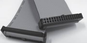
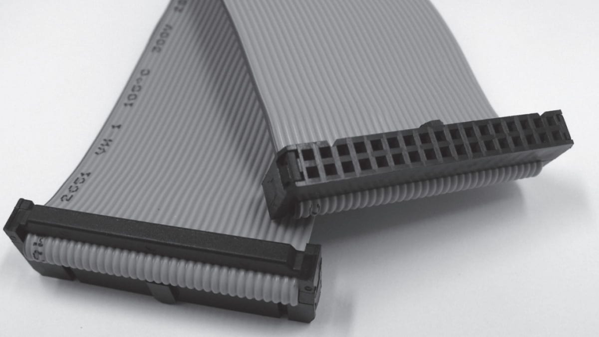
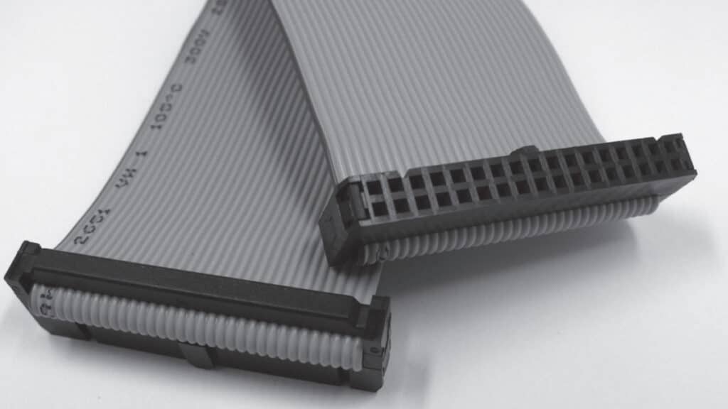
There is an additional signal connector issue to be addressed with respect to IDC connectors, strain relief features. As noted in Chapter II/2.2 Contact Springs. IDC connectors can benefit from strain relief features to diminish the potential for stresses parallel to the axis of the IDC slot disturbing the IDC connection. Some of these features are incorporated into the housing directly while the use of external covers is also an option. Figure 2.106 shows a strain relief cover for an IDC connector.

RelatedPosts

Connectors Explained

KYOCERA AVX IDC RF Shark Fin Connectors for Antennas Vehicle Systems

Binder Launches M12 Panel L-coded Mount Connectors

Fig. 2.106: IDC connector strain relief

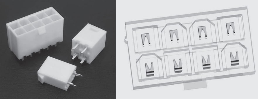
There are two safety related housing design features included in power connectors. Creepage and clearance distances are defined in standards issued by organizations such as VDE and UL. Figure 2.107 illustrates these distances. Clearance is the distance between two contacts in air and creepage is the distance from contact to contact along the surface of the housing. Creepage distance is directed to ensuring that dielectric breakdown of air, arcing, does not occur between contacts. Creepage addresses the potential for electrical degradation of the housing surface resistance of the polymer. A second approach towards the same end is to put the contacts in recesses or silos in the housing. An example of contacts in a recesses and silos is provided in Figure 2.108 One purpose of these features is to “finger proof” the contacts, that is to prevent a finger from shorting across a live contact pair resulting in an electric shock. Contacts within a recess or silo do not have a clearance issue, but creepage distance is still a requirement.

Fig. 2.107: Creepage and clearance distances
Fig. 2.108: Silos and recess in WR-MPC4 family

An additional power connector housing design feature is to provide passages for air flow through the housing for cooling of the contacts to minimize the effects of Joule heating on the contact temperature. An example of such features is shown in Figure 2.109.

Fig. 2.109: Air passage into a WR-MPC4 connector

Related

Source: Wurth elektronik
Next Post

Connector Testing Introduction

Definitions

Generic Test Plan

Popular Posts

  • Crimped Connections

    0 shares
    Share 0 Tweet 0
  • THR (Through Hole Reflow) Technology: Introduction & History:

    0 shares
    Share 0 Tweet 0
  • Basic Principles of Connectors

    0 shares
    Share 0 Tweet 0
  • The Electrical Interface: Contact Resistance

    0 shares
    Share 0 Tweet 0
  • Space Saving Molex Connector in AR/VR System designs

    0 shares
    Share 0 Tweet 0

Subscribe to Blog via Email

Enter your email address to subscribe to this blog and receive notifications of new posts by email.

Archive

2023
2022

Newsletter Subscribe

  • About
  • Inter-Connection Blog
  • Inter-Connection News
  • Knowledge base
  • NEWS
  • Privacy Policy
  • Sister Sites
  • Subscribe

© 2023 EPCI - Premium Passive Components & Inter-Connect News

No Result
View All Result
  • About
  • Inter-Connection Blog
  • Inter-Connection News
  • Knowledge base
    • Applications
    • Basic Principles of Connectors
    • Design Selection Assembly
  • NEWS
  • Privacy Policy
  • Sister Sites
  • Subscribe

© 2023 EPCI - Premium Passive Components & Inter-Connect News

This website uses cookies. By continuing to use this website you are giving consent to cookies being used. Visit our Privacy and Cookie Policy.