Definition
Power Over Ethernet (POE) technology allows VoIP phones, WLAN access, IP camera … to receive power as well as data over existing LAN cabling without modifying the existing system.
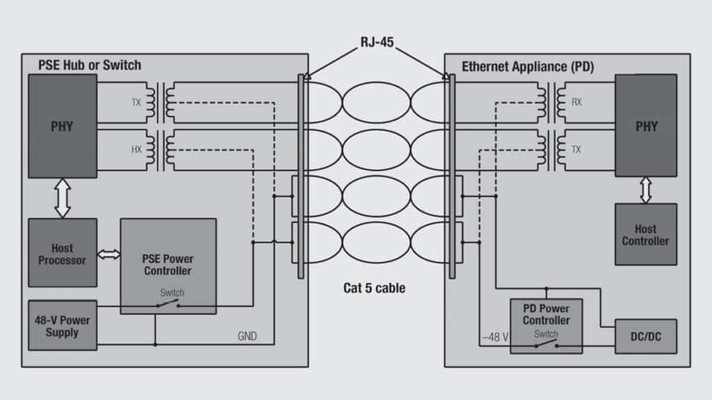
Establishment of an international standard, IEEE802.3af allows an explosion of POE installation all over the world, which was not possible while old proprietary standards were existing together. The cost of adding power supplies to Ethernet switches is getting smaller and smaller. Figure 2.159 shows a typical POE installation.

Today, most electronic applications require both data connectivity and power supply. The most familiar example is telephone which is powered via the same twisted pair that carries the voice since its invention. Did you ever plug your telephone to power before they become hand free?! Of course not so the aim of POE standard is to standardize how to do the same with Ethernet devices without modifying the communication protocol.
There were many technical constraints. A complete recognition protocol had to be defined to detect whether connected systems could receive power (without damaging them), classify their power ratings, and define the way of transmitting voltage and current.
Classification and Applications
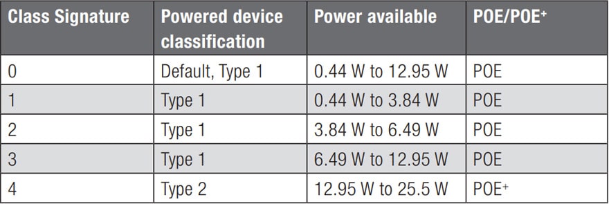
This article does not aim to go into too much detail about POE but the attached classification gives the main characteristics of the POE & POE+ standards (POE+ being able to carry more power, up to 25.5 W like for a bigger IP camera with zoom …)


The IEEE standards are 802.3af and 802.3at respectively for PoE or PoE+.

PSE: (Power Sourcing Equipment) the device that provides power.
PD: (Power Device) this is the device that receives power.
Usually, the distribution is as follows:
PHY side: TD+/–, RD+/–, PHY ground, LED pins (as LED are driven by the PHY)
Cable side: Power pins (PoE), RJ45 pins.
What about modular jacks, what does it imply on this respect?
The key point is the insulation which is carefully controlled and the interface must withstand 1500 Vrms 1 min. PHY side and cable side (remember Figure 2.155) must be insulated from each other.
The distance between RJ45 pins and between RJ45 pins & shielding must be sufficient to stand this voltage. In this case above 1.4mm.
Problems comes often from the LED pins that are in general too close to the shielding.
Summary
To stand POE standard, pins must always have a minimum distance of 1.4 mm between each other and with the shielding too. Special care must be on LED pins which are often too close to the shielding.
A connector does not have absolutely to be used with transformer to be POE compatible (a standard connector without LED should fit) but it is often necessary (for the LED one) since transformer connector designer often included the POE parameter in their concept (much more than the non-filtered one which were developed earlier)


