In a recent white paper, “Millimeter Wave Design: Optimizing Performance in RF Compression Mount Connectors,” Samtec engineers investigate the impact misalignment and pin compression might have on a real-world design. Using modeled and measured data, they explain how to detect and avoid issues and achieve optimized performance in a successful design. Here is a brief summary of their analysis.
Compression mount connectors are a great option for millimeter wave designs because they avoid the problems associated with solder variations. Specifically, the advantages of compression mount connectors (as compared to soldered connections) for millimeter wave designs include avoiding the potential performance degradation of solder reflow, enabling high-performance millimeter-wave frequencies, providing flexibility during PCB design, and offering high reliability. Plus, they can be reused. Designers considering compression mount connectors may wonder how pin compression or misalignment could impact electrical performance.
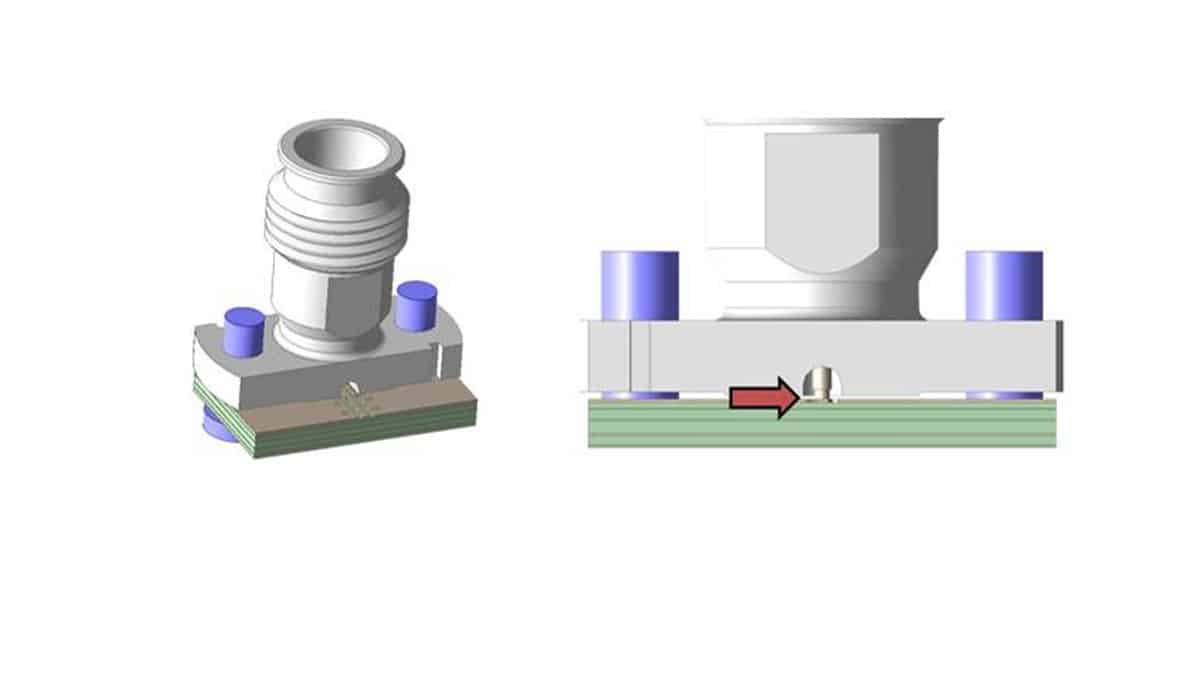
When a compression mount connector is lowered and placed onto a PCB, the signal pin contacts the PCB before the connector body grounds to the PCB copper (featured image). What is important to understand: as we tighten the mounting hardware, does the pin push into the PCB? And if so, does it impact the PCB layers within a degree of concern that will degrade electrical performance of the connector or PCB launch?
The authors performed simulations that suggest bandwidth and performance could be impacted if pin compression occurs. But, how do we know if pin compression occurs? The authors next expanded the study to create detailed models to answer the questions: Can we accurately predict mechanical compression and what do we learn? What is the electrical impact of mechanical deformation and what can be done to minimize that impact?
The paper details the modeling and performance analysis. The surprising risk to electrical performance was unexpected PCB warpage for over-torqued and/or soft PCB materials. Increased PCB warpage could create a cavity between the connector and PCB, with an increase in PCB warpage corresponding to a change in the cavity’s geometry.
Misalignment of Compression Mount Connectors
The remaining concerns for compression mount connectors have to do with misalignment. There are three degrees of freedom in how a compression mount connector could be misaligned: side to side, back and forth, and rotational. The authors examined how these types of misalignments could influence performance (see the white paper for details on this analysis).
While it is reasonably easy to see rotational misalignment, it is nearly impossible to see back and forth misalignment, which was shown to be the most sensitive parameter. So how can a designer ensure that a connector pin is placed properly on the pad?
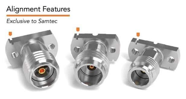
To address this concern, Samtec has added alignment features to connectors, which appear as notches in the corner of Samtec’s vertical compression mount connectors (see Figure 1). These work in conjunction with a fiducial that can be etched into the PCB.
Final Takeaways
When using compression mount connectors, it is important to remember these key points:
- Mechanical pin compression can occur, but PCB warpage might occur first
- PCB warpage can lead to electrical suckouts
- For maximum performance, follow the recommended mounting torque and visually inspect for warpage, particularly around the edge of the connector
- For maximum performance and ease of installation, use compression mount RF connectors that are equipped with alignment features


