Mechanical conditioning are intended to assess the mechanical stability of the contact interface under field conditions. As noted previously in this chapter, disturbances of the contact interface can be driven by either thermal or mechanical forces. The thermal forces result indirectly from thermal expansion mismatch stresses, thermal cycling or thermal shock, while the mechanical forces are applied directly, mechanical shock or vibration.
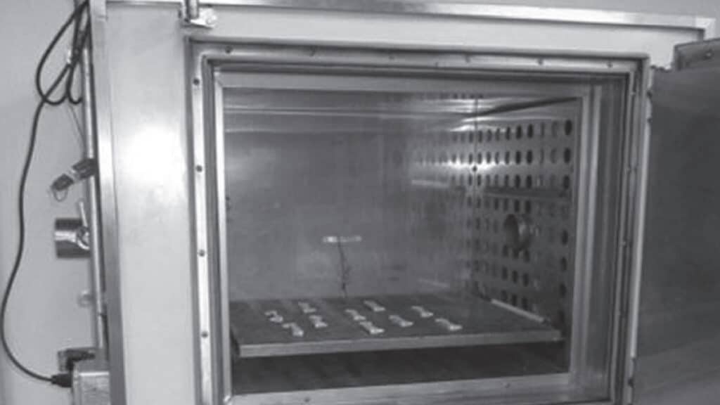
The difference between thermal cycling and thermal shock is the rate of change of temperature between the upper and lower temperature limits. Thermal cycling is generally a slow change in temperature, often by cycling either the applied current or the oven temperature, while thermal shock is generally rapid by moving the samples between chambers at different temperatures. An oven suitable for thermal cycling is shown in Figure 2.116 and a dual chamber, thermal shock oven, in Figure 2.117.
Thermal shock is further differentiated by the different thermal response times of the connector and system components. While the magnitude of the applied stresses may be the same for a given temperature change, the rate of application of the stresses in thermal shock is generally a more demanding environment. The thermal stresses realized are dependent on the size of the connector because the differential change in length is dependent on the length of the connector or system. This fact should be taken into consideration when selecting the samples to be tested. Table 2.7 lists typical conditions of thermal shock.
Mechanical shock is generally intended to simulate transportation stresses, though there are some connector environments, e.g. automotive that experience mechanical shocks as a part of their application environment. The G values and number of shocks applied are application dependent.
