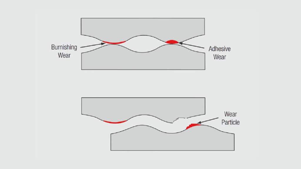
Friction and wear are two aspects of the same basic kinetic process. Friction forces must be overcome to cause motion, and motion must occur to cause wear. Consideration of Figure 1.17 will be used to explain this statement.
Consider Figure 1.17 through a thought experiment where two a-spot contacts are created. The a-spot on the right is created first under a given applied load. The individual asperities deform against each other under the load. Four things happen during the deformation. First, the asperities deform plastically due to their small size causing material flow. Surface films and contaminants are disrupted or displaced on the microscale of the flow. Second, the clean metal surfaces exposed due to the microflow can form cold welded junctions when the microflow ceases. Third, the asperity surfaces work harden due to the deformation. Fourth, the a-spot contact area increases as the load increases.
While all this is happening at the first asperity contact the surfaces are continuing to come closer to one another and the second a-spot is created. The same process then begins to take place at this second a-spot. We now have two a-spots that have experienced different amounts of deformation. The difference in deformation means that the first a-spot is larger, due to more metal flow, and stronger – due to a greater work hardening response and more cold welding.
The increased area and strength of the first a-spot means that it will be mechanically more robust. Consider how the two a-spots will respond under an applied shear stress. This discussion is qualitative and only serves to illustrate the kinetics of friction and wear.
The applied shear stress will not lead to motion of the interface until the a-spots are broken. Given that the first a-spot is larger and stronger, it will determine the stress necessary to break the interface and cause motion. The necessary stress is related to he friction force of the contact interface. Thus the a-spot structure and distribution determines the friction force and, therefore, the mechanical stability of the contact interface.
The kinetics of separation at the a-spot interfaces will be different as well. Recall that the interface of the first a-spot is stronger than that of the second. In fact, due to work hardening and cold welding, the interface may be even stronger than the cohesive strength of the base metal. In such cases, the a-spot interface may break within the base metal rather than at the interface resulting in a wear particle as indicated in Figure 1.17. Such wear processes are commonly referred to as adhesive wear. In contrast, the weaker interface of the second a-spot may break at or near the original interface without a wear particle being generated. Wear of this type is referred to as burnishing wear. The wear track in a connector experiencing adhesive wear, sometimes called galling wear, will be rough, while that of burnishing wear will be relatively smooth.
The significance of wear processes in a connector is straightforward. Wear results in the loss of surface material. If a connector is designed to take advantage of the benefits of a contact finish, wear can lead to loss of the contact finish at the mating area and a consequent decrease in performance. This is particularly significant when the small thicknesses of contact finishes are recognized. Susceptibility to wear is one reason connectors are rated for a specific number of mating cycles.
Friction has two effects on connector performance, one positive and one negative. The positive effect is that friction provides mechanical stability of the contact interface against forces tending to drive motion of the connector. Disturbances of the contact interface can be a significant degradation mechanism for a connector for two reasons. First, the micromotions of a contact disturbance can induce wear at the contact interface. Second, micromotions can drive corrosion mechanisms, especially in tin finished contacts, and can lead to bring corrosion products and contaminants around the contact area into the contact interface. Thus high friction forces, generally due to high contact normal forces, can have a positive effect on connector performance.
There are two negative effects of friction forces. First, high friction forces correlate directly with wear mechanisms as has been discussed. Second, high coefficients of friction will increase the mating force of a connector. Mating force varies directly with the coefficient of friction.
These issues, friction, mating force, contact force and wear will be discussed in detail in Chapter II/2.2.1 Separable Interface Requirements.
