The following discussion provides a basic overview of the stages of electrodeposition during a reel-to-reel strip plating process. The manufacturing processes leading to reels of stamped and formed contacts will be described in Chapter II. The function of each stage will be described, but the details of accomplishing the function are not included because, as noted previously, electroplating practices are highly proprietary.
Stage 0 – Incoming inspection:
While inspection of the incoming reel is independent of the electroplating process, it is not overstating to say that the quality of the electroplate is controlled by the quality of the incoming reel. Successful electroplating requires a “clean” metal surface and an incoming reel with residual stamping oil, scratches or stamping damage and base metal defects may be impossible to plate so as to produce a smooth, continuous and defect free plating.
Stage 1 – Precleaning:
Given the previous comment on surface cleanliness it is not surprising that the first stage of the electroplating process is to clean the contacts. Many different cleaning processes may be included in this stage, ultrasonic organic cleaning to remove residual stamping oils or contaminants, acid, electrocleaning/electropolishing etc. A rinsing station may be included between each of the cleaning stages as well. Cleanliness is critical to electroplating success.
Stage 2 – Plating:
The desired metal is now electroplated onto the cleaned contacts. While the need for a nickel underplate with gold contact finishes has been emphasized, there are other reasons for using an underplate with other finishes. For example a thin layer of copper may be applied as a “strike” to facilitate adhesion onto some copper alloys, or a thicker layer may be used to smooth the surface, a leveling copper. The same electroplating practices will be used for these supplementary platings as for the finish plating. Plating bath pH , composition and temperature are carefully monitored during the electroplating process.
Stage 3 – Rinse/Dry:
On completion of electroplating the contacts are rinsed and dried before being rereeled and sent on to the next stage of the manufacturing process. Rinsing is important because residual plating solution and salts can cause corrosion of the contacts if not removed.
Multiple “Stage 2” stations can be used for multiple layer platings, gold over nickel, and, if so, it is necessary to ensure that the plating solutions do not transfer from one station to the next so a rinse station is generally included between all plating stations. In the case of gold over nickel platings, it is essential that the contacts do not dry out between the nickel and the gold stations because nickel exposed to air “passivates”, forms a thin oxide layer, inhibiting the effective plating of the following gold plate.
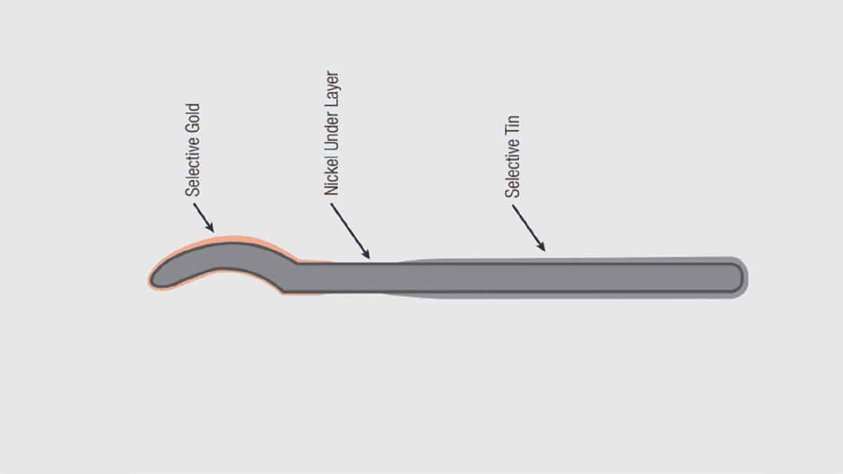
A few comments on selective and duplex plating are in order at this point. Figure 1.23 illustrates a contact which is both selectively and duplex plated. The first plating applied is an overall nickel underplate, that is, the entire contact surface is plated with nickel. The second plating applied is a selective gold at the mating interface, a. The third plating is a selective tin, b, at the contact tail to provide a solderable surface.

The selective plating is obvious; the tin and gold platings are applied only where needed for functionality. The contact is duplex plated because two separate areas have been plated. In this example the two platings are different, gold over nickel and tin over nickel. In some cases a gold flash is used to preserve the solderability of the contact tail section. This combination would also be considered duplex plating. If the gold flash was used, the contacts could be plated using two separate gold plating stages in the same configuration in the plating bath. The anode/cathode location and geometry would be positioned appropriately in the plating bath to plate desired areas and thicknesses. In the case of duplex tin, however, it is common to apply the gold plating and then invert the contacts in a transition stage before immersing only the contact tails into a supplementary bath to plate the tail section with tin.
The photo of Figure 1.24 show different plating bath (a) Ni, b) Tin and c) where the bandolier pins are rotated to perform selective plating.


