• Latest
  • Trending

Solder Reflow Practice

September 13, 2022

Samtec New Interconnects Enhances Power and Signal Integrity

March 21, 2023

PCB Via Design Selection; Plugging-Filling-Tenting

March 20, 2023
PCNS Passive Components Symposium 11-14th September 2023

Lemo Releases New Multi Coaxial High Frequency Connector

March 2, 2023

Würth Elektronik Introduces Crimp SKEDD Connectors

March 1, 2023

binder Offers Sensor Connectors in Stainless-Steel to Protect Against Corrosion

March 1, 2023

Board-to-Board Connection & Antennas HF Connection

February 20, 2023

How to Ensure Board-to-Board Connectors Meet High-Speed Automotive Assembly and Use Requirements

February 16, 2023

Amphenol Enhanced its ePower-Lite EV Line to Include 3-Pole Connector

February 15, 2023

BASIC PCB Design Rules – Layout

February 15, 2023

Connector Inrush Current Explained

February 3, 2023

M8 Connectors for Smart Farming Applications

January 31, 2023

binder Extends its M12 Connector Lines

January 31, 2023
  • Privacy Policy
inter-connection blog
  • NEWS
  • Knowledge base
  • Sister Sites
    • Passive Components Blog
    • PCNS Symposium
    • The Passives Times
    • EPCI Home
  • About
No Result
View All Result
  • NEWS
  • Knowledge base
  • Sister Sites
    • Passive Components Blog
    • PCNS Symposium
    • The Passives Times
    • EPCI Home
  • About
No Result
View All Result
inter-connection blog
No Result
View All Result

Solder Reflow Practice

September 13, 2022
A A

As noted previously, the THR reflow practice is basically identical to the SMT reflow practice. As such, it can be accomplished through infra-red convection and vapor phase soldering. In either case, the temperature profile of the reflow soldering process is critical to a consistent and reliable reflow soldering. Figure 2.100 shows a representative temperature profile recommended for lead free infra-red convection reflow soldering according to IPC/JEDEC J-STD 020D.

Fig. 2.100: Temperature profile for lead-free infra-red convection reflow soldering per IPC/JEDEC

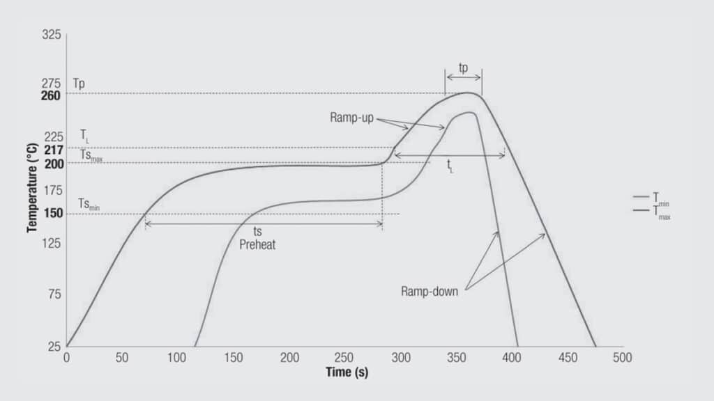
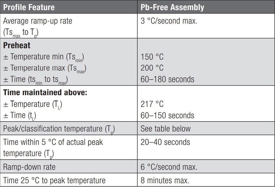
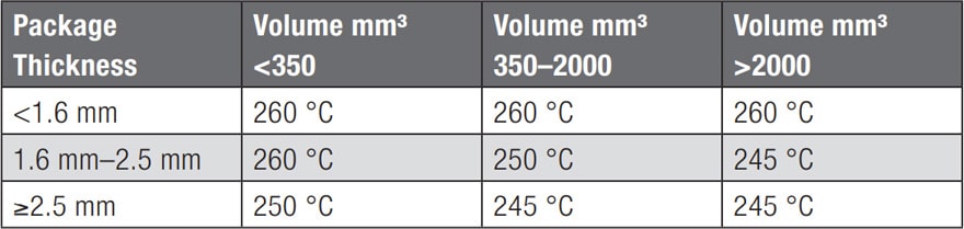
Process details are provided in Table 2.5. Peak temperature recommendations are provided in Table 2.6

Tab. 2.5: Reflow profile details
Tab. 2.6: Connector size dependent parameters

Related

Source: Wurth elektronik
Next Post

Soldering Quality

Connector Housings Overview

Material Selection

Popular Posts

  • Crimped Connections

    0 shares
    Share 0 Tweet 0
  • Basic Principles of Connectors

    0 shares
    Share 0 Tweet 0
  • Space Saving Molex Connector in AR/VR System designs

    0 shares
    Share 0 Tweet 0
  • THR (Through Hole Reflow) Technology: Introduction & History:

    0 shares
    Share 0 Tweet 0
  • The Electrical Interface: Contact Resistance

    0 shares
    Share 0 Tweet 0

Archive

2023
2022

  • About
  • Inter-Connection News
  • Knowledge base
  • NEWS
  • Privacy Policy
  • Sister Sites

© 2023 EPCI - Premium Passive Components & Inter-Connect News

No Result
View All Result
  • About
  • Inter-Connection News
  • Knowledge base
    • Applications
    • Basic Principles of Connectors
    • Design Selection Assembly
  • NEWS
  • Privacy Policy
  • Sister Sites

© 2023 EPCI - Premium Passive Components & Inter-Connect News

This website uses cookies. By continuing to use this website you are giving consent to cookies being used. Visit our Privacy and Cookie Policy.