• Latest
  • Trending

Soldering Quality

September 13, 2022

binder Unveils Quick Lock Ruggedized Power Bayonet

October 3, 2023

Connector Temperature Rise and Derating

September 29, 2023

Connector Raw Material Costs Decreased 6.9 Percent in Q2 2023

September 27, 2023

Webinar PCBs: RIGID.flex with Flexible Soldermask or Coverlay?

September 20, 2023

Samtec Expands with a New Cable and RF Connector Manufacturing Facility in Pennsylvania

September 20, 2023

KYOCERA AVX Unveils New Series Poke-Home Single Contacts

September 20, 2023

Murata Announced Completion of New Plating Research Building in Japan

September 19, 2023

RF Compression-Mount Connectors Enhance Millimeter Wave Designs

September 1, 2023

Würth Elektronik Introduces micro SIM Card Interface with Card Detection

August 31, 2023

Yamaichi Extended Board-to-Cable Connectors for Battery Management

August 15, 2023

How the Connector Blade Assignments Impact Power Integrity 

August 15, 2023

How to Maintain 50 Ohms RF Transmission Path

August 15, 2023
  • Privacy Policy
inter-connection blog
  • Home
  • Knowledge base
  • Sister Sites
    • Passive Components Blog
    • PCNS Symposium
    • The Passives Times
    • EPCI Home
  • About
No Result
View All Result
  • Home
  • Knowledge base
  • Sister Sites
    • Passive Components Blog
    • PCNS Symposium
    • The Passives Times
    • EPCI Home
  • About
No Result
View All Result
inter-connection blog
No Result
View All Result

Soldering Quality

September 13, 2022
A A

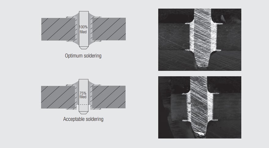
As per the IPC-A-610D, a compliant solder joint must fill at least 75% of the free volume between the pin and the PCB hole and there must be less than 25% of air cavity. Figure 2.103 illustrates the soldering joint acceptability.

Fig. 2.103: Acceptable soldering joints

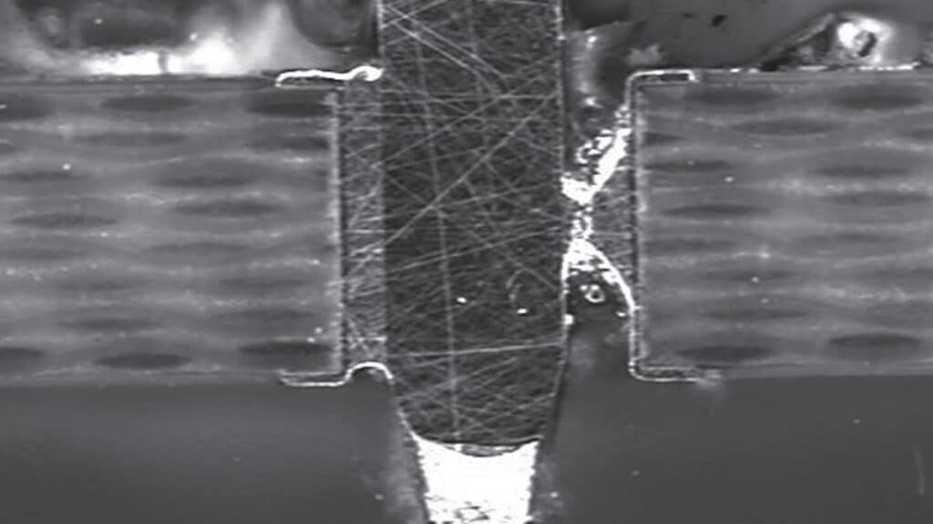
If the requirement for pick and place and solder paste application process are not complied with, then the quality might be affected and it might produce defects due to insufficient solder paste resulting from: a) incorrect solder paste calculation, b) improper PTH/pin volume or c) inappropriate screen printing machine settings. Figure 2.104 shows an example of insufficient solder paste.

RelatedPosts

Connectors Explained

KYOCERA AVX IDC RF Shark Fin Connectors for Antennas Vehicle Systems

Binder Launches M12 Panel L-coded Mount Connectors

Fig. 2.104: Unacceptable soldering joints: poor solder joint

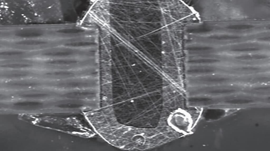
Defects may also be caused by an excess of solder paste as per Figure 2.105.

Fig. 2.105: Unacceptable soldering joints: solder paste excess

Related

Source: Wurth elektronik
Next Post

Connector Housings Overview

Material Selection

Housing Design

Popular Posts

  • Crimped Connections

    0 shares
    Share 0 Tweet 0
  • THR (Through Hole Reflow) Technology: Introduction & History:

    0 shares
    Share 0 Tweet 0
  • Basic Principles of Connectors

    0 shares
    Share 0 Tweet 0
  • The Electrical Interface: Contact Resistance

    0 shares
    Share 0 Tweet 0
  • Space Saving Molex Connector in AR/VR System designs

    0 shares
    Share 0 Tweet 0

Subscribe to Blog via Email

Enter your email address to subscribe to this blog and receive notifications of new posts by email.

Archive

2023
2022

Newsletter Subscribe

  • About
  • Inter-Connection Blog
  • Inter-Connection News
  • Knowledge base
  • NEWS
  • Privacy Policy
  • Sister Sites
  • Subscribe

© 2023 EPCI - Premium Passive Components & Inter-Connect News

No Result
View All Result
  • About
  • Inter-Connection Blog
  • Inter-Connection News
  • Knowledge base
    • Applications
    • Basic Principles of Connectors
    • Design Selection Assembly
  • NEWS
  • Privacy Policy
  • Sister Sites
  • Subscribe

© 2023 EPCI - Premium Passive Components & Inter-Connect News

This website uses cookies. By continuing to use this website you are giving consent to cookies being used. Visit our Privacy and Cookie Policy.