inter-connection blog
  • Home
  • Knowledge base
  • Sister Sites
    • Passive Components Blog
    • PCNS Symposium
    • The Passives Times
    • EPCI Home
  • About
No Result
View All Result
  • Home
  • Knowledge base
  • Sister Sites
    • Passive Components Blog
    • PCNS Symposium
    • The Passives Times
    • EPCI Home
  • About
No Result
View All Result
inter-connection blog
No Result
View All Result

The THR Manufacturing Process

September 12, 2022
A A

The basic requirement of a THR manufacturing process is to ensure compatibility with the existing SMT manufacturing process, typical stages of which are illustrated in Figure 2.86.
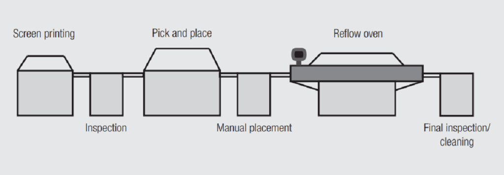
Fig. 2.86: Stages of a typical SMT/THR manufacturing line

Stage 1: Screen printing: the solder paste is applied to the PCB.
Stage 2: Inspection: ensures the dimensional control and alignment of the screen printing process with the PCB.
Stage 3: Pick and place: puts the SMT, and any connectors which may also be pick and place compatible, onto the screened solder paste.
Stage 4: Manual placement: connectors are manually inserted into the PTH of the PCB.
Stage 5: Reflow oven: reflow soldering of the components onto/into the PCB via reflow soldering processes, typically vapor phase or convection reflow.
Stage 6: Final inspection: inspection using appropriate methods to ensure the proper placement of components and satisfactory soldered joints.
Stage 7: Cleaning: removes possible flux residues.

RelatedPosts

What is RF Connector

Connectors Explained

KYOCERA AVX IDC RF Shark Fin Connectors for Antennas Vehicle Systems

Figure 2.87 shows the status of the PCB with respect to the solder paste and soldering process through the manufacturing line. The first three illustrations show processes occurring in the screen printing stage as the solder paste is applied to the PCB, the fourth illustration shows the PTH after the connector insertion with the solder paste distribution in the PTH, the last two illustrations show the reflow process and the configuration of the soldered component.
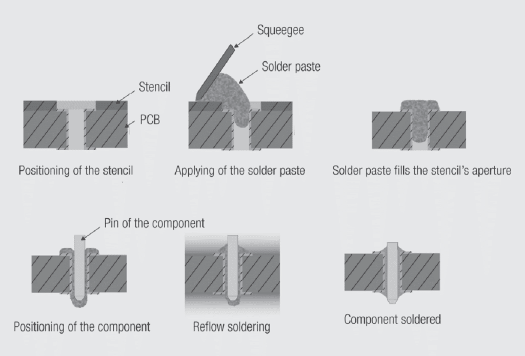
Fig. 2.87: Stages of printing and soldering THR processes

Related

Source: Wurth elektronik
Next Post

Screen Printing

Solder Paste Volume

Solder Paste Application

Popular Posts

  • Crimped Connections

    0 shares
    Share 0 Tweet 0
  • The Electrical Interface: Contact Resistance

    0 shares
    Share 0 Tweet 0
  • Test Explanations: Connector Resistance

    0 shares
    Share 0 Tweet 0
  • THR (Through Hole Reflow) Technology: Introduction & History:

    0 shares
    Share 0 Tweet 0
  • Basic Principles of Connectors

    0 shares
    Share 0 Tweet 0

Archive

2023
2022

  • About
  • Inter-Connection Blog
  • Inter-Connection News
  • Knowledge base
  • NEWS
  • Privacy Policy
  • Sister Sites
  • Subscribe

© 2023 EPCI - Premium Passive Components & Inter-Connect News

No Result
View All Result
  • About
  • Inter-Connection Blog
  • Inter-Connection News
  • Knowledge base
    • Applications
    • Basic Principles of Connectors
    • Design Selection Assembly
  • NEWS
  • Privacy Policy
  • Sister Sites
  • Subscribe

© 2023 EPCI - Premium Passive Components & Inter-Connect News

This website uses cookies. By continuing to use this website you are giving consent to cookies being used. Visit our Privacy and Cookie Policy.
Go to mobile version